Summary. This page explains how to use PTAssembler to create panoramas using images that were taken from a camera that was not rotated around its entrance pupil (sometimes called "nodal point").
Introduction. Ideally, when taking the photographs to be assembled into a panorama, the camera should not be moved. The camera should be rotated around its entrance pupil so that the resulting images are completely free of parallax errors (visible when the foreground appears to shift in relation to the background). If the camera is not rotated around the entrance pupil, then the images cannot be perfectly aligned because of these parallax errors...some portions of the images can be aligned, but not all. If the camera movement is small enough, it is often possible to disguise (although not remove) these errors with careful blending.
However, PTAssembler's "camera position optimization" (CPO) feature now makes it possible to align images taken from different positions, as long as the image is a flat surface (i.e. a plane). In this case, it is possible to align the plane with the rest of the image regardless of how far the camera is moved between captures. Even if the entire image isn't a plane, it is still possible to align the portion of the image that is a plane with the rest of the panorama.

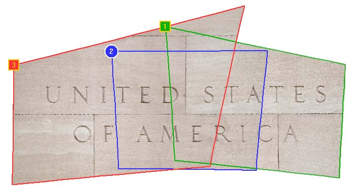
3 images taken from different locations
3 images remapped after camera position optimization, shown in PTAssembler's preview viewer
Conceptual Overview. In order to explain how the CPO logic works, and what it does, it is necessary to understand a little about how PTAssembler positions images in a project so that they are correctly aligned. In the absence of CPO, PTAssembler's internal model assumes that the camera is located at the center of an imaginary sphere. PTAssembler's stitcher remaps and positions (using the yaw, pitch and roll parameters calculated by PTAssembler's optimizer) all of the images in the project onto the interior surface of this imaginary sphere. (Imagine yourself standing inside at a point in the exact center of a giant sphere, looking around at the interior surface where the images have been displayed onto its surface).
Once this positioning has happened, the images are then "projected" from the surface of the sphere onto the final two dimensional output surface (i.e. the computer monitor). As long as the camera is rotated around the entrance pupil when the images are captured, this works fine...each image can be positioned at the correct location on the sphere's interior surface; all that the stitcher needs to know are the images' yaw, pitch and roll parameters.
Camera Position Parameters. If the camera is moved between shots, then the yaw, pitch and roll parameters are no longer sufficient by themselves to describe where on the surface of the imaginary sphere an input image should be positioned. In this case, the stitcher also needs to know where the camera is positioned inside the imaginary sphere and its orientation. Luckily, you don't need to know this information, because the optimizer can be configured to deduce it from the information that is provided by control points. The basic idea, then, behind PTAssembler's CPO is to perform an intermediate transformation of the image (using the "camera position parameters") before remapping and positioning that intermediate image onto its final location in the panorama. This intermediate transformation converts the image to look like one that would have been captured if the camera had been positioned at the center of the sphere. Note that, in practice, this intermediate transformation happens as part of the stitching process and is never actually output by the stitcher, so there is no quality loss due to multiple transformations.
To sum up the story so far: The camera position parameters allow PTAssembler to perform an intermediate rotation (camera yaw, camera pitch) followed by a shifting (camera X, Y and Z) of the image before it is positioned (using yaw, pitch and roll) at its final location in the panorama. It is this intermediate rotation and shifting that transforms the image into a shape that allows it to be positioned at the correct point on the sphere and align with neighboring images, even if those neighboring images were taken from different locations.
Using Camera Parameter Optimization. Camera Position Optimization is configured on the "Camera Position Parameter Configuration" dialog, accessible by clicking the "Camera Position..." button on PTAssembler's Step 4 screen. The "Camera Position Parameter Configuration" screen allows you to choose which camera position parameters to optimize (more below), and reset or update any camera position parameter values. Because CPO is something of an advanced technique (and one that is not generally used as a part of most panoramic image creation), PTAssembler's "auto-create" and "auto-optimize" buttons will not perform any optimization of these parameters...in order to make use of CPO, you'll have to select the parameters to optimize yourself, and run the optimizer manually.
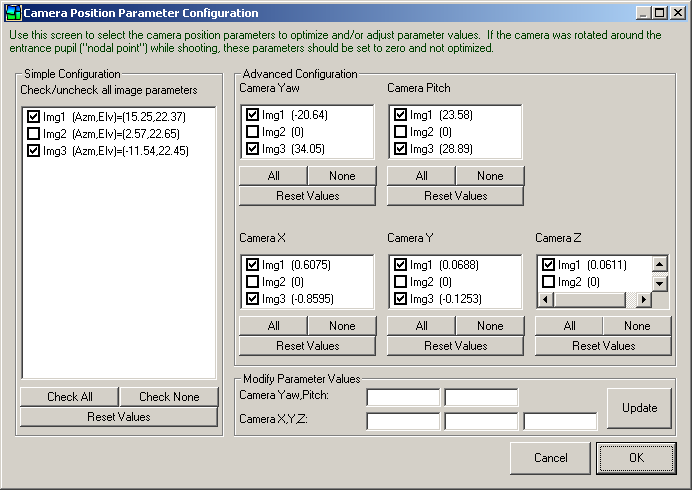
Camera Position Parameter Configuration screen.
Before making use of this screen, however, you should make sure that all images in the project have sufficient control points set. It is important to reiterate that if CPO is used, then only a single flat surface (plane) in images that were taken from different positions can be aligned with the rest of the image. If the scene contains objects that lie in different planes, you should only set control points on objects in a single plane, otherwise the optimizer will not be able to deduce good estimates for the camera position parameters, and the stitcher will not be able to position the image correctly.
Depending on how far the camera was moved between shots, you may have to create control points manually, as the automated control point picker programs may have difficulty determining corresponding objects in overlapping images. Also, because CPO requires the optimizer to estimate values for several camera position parameters (in addition to the standard yaw, pitch and roll parameters), it is important to give the optimizer plenty of control points to work with. As a rule of thumb, you should aim to set at least 10 (more is often better) well spaced (i.e. not all clustered in a bunch) control points on each image where the camera position was changed. The optimizer uses these control points to deduce the "best fit" values for yaw, pitch, roll and any selected camera position parameters.
Checking/unchecking a box in the "Simple Configuration" frame at the left of this screen will check/uncheck all parameters for the corresponding image in the "Advanced Configuration" frame at the right of the screen. Similarly, the check all/none buttons can be used to quickly check/uncheck multiple parameters and/or images simultaneously. If one or more images are highlighted in the simple configuration frame, values for those images can be edited/updated using the "Modify Camera Parameters" frame that the bottom of the screen. Current values for each parameter are also displayed in parentheses next to each image name in the individual parameter selection boxes.
If CPO is used, then the standard yaw, pitch and roll values by themselves no longer tell you where (on the surface of the imaginary sphere) the image will be positioned. However, next to each image name in the simple configuration frame, the azimuth ("Azm") and elevation ("Elv") of each image's position on the sphere is displayed. (Azimuth and elevation are equivalent to longitude and latitude.) This information allows you to guage the relative positioning of each image in the final panorama.

11 images taken of a mural, each image from a different location

11 images merged after camera position optimization in PTAssembler
Tips, Tricks and Strategies. In general, you should optimize five camera position parameters (Camera Yaw, Camera Pitch, Camera X, Camera Y and Camera Z) for each image in the project where the camera was moved between shots (i.e. for any images where the camera wasn't rotated around the entrance pupil). In one case, however, it is sufficient only to use the Camera X, Y and Z parameters: where the image doesn't need to be rotated with the camera yaw and camera pitch parameters to be in the same plane as the panorama. This is generally the case if the panorama has been optimized using horizontal and vertical line control points. If in doubt, use all the camera position parameters.
The optimizer uses an iterative process to converge upon a "best fit" solution. Without delving in the mathematics of the optimization process, it is worth noting that this process is influenced by the starting point of the parameter values. It is possible for the optimizer to arrive at different solutions depending on the starting position (supplied via the initial parmeter values). In some cases you may have better luck optimizing all the camera position parameters at the same time as all of the "regular" yaw, pitch and roll parameters. In other cases, it may work best if the regular yaw, pitch and roll parameters are optimized first, before including the camera position parameters in the set to be optimized. Some experimentation may be necessary. If an initial parameter value is very far away from its correct (or even reasonable) value, the optimizer may never be able to converge upon a good solution. For this reason, if you are having trouble getting a good result out of the optimizer, you may want to examine all of the current parameter values (including lens distortion and field of view) to see if any of these values lookly obviously wrong and reset their values before optimizing again.
In all cases, it is true that at least one of the images should be left with its camera position unoptimized to act as an "anchor" or "reference" image. If all of the camera position parameters are optimized for all of the images, the optimizer may converge upon a mathematically "optimal" solution that does not give visually correct results.
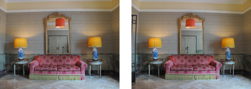
2 images taken of hotel lobby, from slightly different locations...camera and tripod reflected in mirror
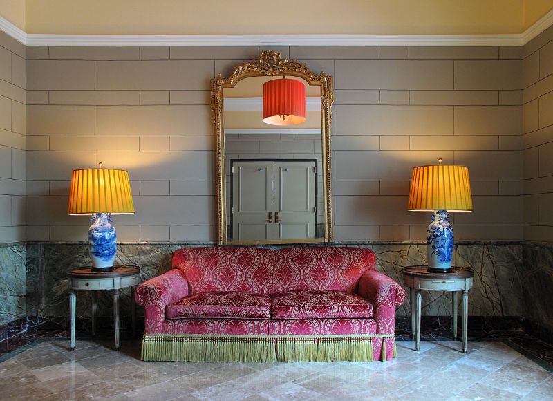
2 images remapped and manually blended to remove reflection of camera and tripod
Applications and Uses. There are a number of useful and interesting applications for this feature:
- Patching the "nadir" in a 360 degree spherical panorama. When taking a 360 degree spherical panorama, you may take the "nadir" shot (i.e. pointing down at the ground) from a handheld position so as not to include the tripod legs in the image. Given that the ground is usually a flat plane (or close enough), CPO can be very helpful in aligning this shot with the other images in the scene.
- Handheld panoramas. Hand-held panoramas are a good candidate for this feature, particularly those where the scene is of a flat surface (e.g. the front of a building, or a piece of art hanging on a wall).
- Removing obstructions and unwanted elements. There are a number of artistic uses for which this technique can be employed wherever it might be advantageous to assemble a scene using images taken from different vantage points. For example, you can use this to remove the photographer's own shadow from a scene by taking a second shot (from a different vantage point) of the portion of the scene where the photographer's shadow falls. A similar approach can be used to remove reflections from mirrors or windows, or obstructions in from of the subject (e.g. a lamp post in front of a building).
- Flat surface panoramas. If the surface of the subject is flat, you can move the camera from location to location while shooting. For example, you might wish to capture all the storefronts in the length of a city block. Leaving the camera stationary would make this a difficult proposition, but you could move the camera along the block while photographing each store "head on", and use this feature to assemble the results into a long panoramic image.
- Assembling scanned images of maps or artwork. The camera position parameters can be used to assemble portions of maps or artwork into seamless composite.
More Reading. For more information and help with PTAssembler, please consult the complete PTAssembler documentation.