- Introduction
- Main Screens (Step by step):
- Other Screens:
- Processing Options Screen.
- Preview Viewer/Editor Screen.
- Exposure, Whitebalance and Vignetting ("Photometric") Adjustment Screen.
- Photometric Settings Screen.
- Reference Point Picker Screen.
- Preferences Screen.
- Files/Dirs Tab.
- Display Tab.
- Behavior Tab.
- Advanced Tab.
- Plugins Tab.
- Misc Tab.
- Autocreate Tab.
- GPS Tab.
- Optimizer Configuration Screen.
- Camera Position Parameter Screen.
- GREYCstoration Configuration Screen.
- Properties Screen.
- Batch Processing Screen.
- Control Point Information Screen.
- Lens Presets Screen.
- Lens Calculator.
- Numeric Transform.
- Menu Options:
- Autocreate
- Autoalign
- Processing Workflow Overview
- A Note About Output Size
- Command Line Options
- GPS and Location Features
- Bugs and Problems
- Links and More Reading
PTAssembler is a Windows program that "stitches" digital images into larger "panoramic" and/or "mosaic" images. (The term "mosaic" is generally used to refer to a panoramic image that consists of multiple rows of images, rather than a single row "panoramic" image). PTAssembler makes no distinction between mosaics and panoramas -- the program doesn't need to -- but photographers often consider these two types of images differently. This document uses the terms interchangeably.
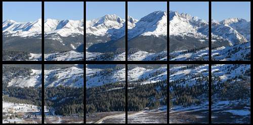
Layout image showing a project with 12 images
PTAssembler is designed to lead the user through the process of creating a panoramic or "stitched" image in five steps. These five steps are reflected in PTAssembler's five main screens. The basic procedure for creating a stitched image is:
- Step 1. Load the source images into the project.
- Step 2. Enter several parameters that describe your camera lens, such as field of view and lens type.
- Step 3. Identify "control points" (common features in overlapping regions of adjacent images) for all images in the project.
- Step 4. Use the control points to "Optimize" the project, i.e. to estimate the position (Yaw, Pitch and Roll, and perhaps other) parameters for each image.
- Step 5. Use these "optimized" parameters to "process" the source images and create a final panorama.
PTAssembler includes a feature that allows the completely automatic creation of stitched images. This feature is called "Autocreate." Please consult the Autocreate section for details on how to use this feature and its limitations. While Autocreate works well for most images, you may find that you wish for more control over the resulting output image. For complete creative control over PTAssembler's output, or in cases where PTAssembler's Autocreate feature fails to produce the desired output, you can still operate PTAssembler manually. Reading this document will help you understand how to operate PTAssembler manually, rather than relying on autocreate.
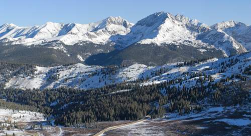
Final image created by combining 12 images into a single mosaic
A note about installation and setup. Older versions of PTAssembler relied upon Panorama Tools as its "engine" to transform input images into a panorama, but this is no longer the case. PTAssembler now has its own stitching engine, called "PTAStitcher". Similarly, PTAssembler no longer relies on the Panorama Tools optimizer program, because PTAStitcher can perform all necessary optimization duties. In short, PTAssembler no longer requires Panorama Tools for any purpose.
PTAssembler is still compatible with the Panorama Tools engine: the optimizing program (PTOptimizer.exe), and stitching program (either PTStitcher.exe and/or PTMender.exe). In general, there is no reason to use these older, slower programs unless you need access to some of the more exotic/unusual features (e.g. morph-to-fit) offered by these programs. Some of PTAssembler's screens and options vary depending on which program is configured as the stitching and/or optimizing program. For example, the morph-to-fit options on the step 2 screen are not present when PTAStitcher is selected because PTAStitcher does not support this feature. Similarly, the PSB output file format is only available when PTAStitcher is selected as the stitching engine because none of the other stitching programs support this file format. If you want to use the Panorama Tools programs, PTOptimizer.exe, PTStitcher.exe and PTMender.exe, they are installed in a subdirectory of PTAssembler's directory, called "PanoTools". Another file (pano12.dll) is installed in the Windows system directory, but will not overwrite any existing versions without prompting you to do so.
PTAssembler stores configuration information in a file called "ptasmblr.ini". This file is stored in the system application data area. If multiple versions of PTAssembler are installed on one machine, they will all share the same ptasmblr.ini file.
Auxiliary plugin programs. In the simplest mode of operation, the user manually identifies control points, optimizes the project and runs the stitcher (PTAStitcher, by default) to create a final output "stitched" image. The images are remapped and rudimentary seam blending (between adjacent images in the project) is performed to create a final output image, but no other functions are performed and no other programs are necessary.
However, PTAssembler's capabilities can be significantly enhanced with additional, optional, programs. A complete list of the auxiliary programs that can be invoked by PTAssembler is provided in the table below. These programs are all "optional" because the steps that they automate can also be performed manually, or are not a mandatory part of the panorama creation process. With the exception of TuFuse and PTAPicker (which are distributed with, and part of PTAssembler), these auxiliary programs are not distributed with PTAssembler. See the downloads section at the end of this document for information on where to download these programs. Once you have downloaded one or more of these programs (and installed or extracted them from any zip files or other archives), you must tell PTAssembler about the location of the program(s) using the Plugins tab of the preferences screen. See also the section on Processing/Workflow for more information about these programs.
Note that, in general, you only need one program from each category. For example, although PTAssembler supports several different control point picker programs, only one is needed in order to automate the control point picking process.
The following table summarizes the suite of external/helper/auxiliary programs with which PTAssembler is designed to operate.
|
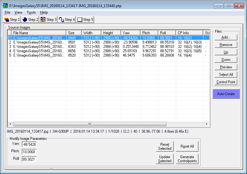
Screen overview. Use this screen to load the source images for your panorama. To add or remove images to your project use the 'add' and 'remove' buttons (PTAssembler can display JPEG and TIFF files). You can also drag-and-drop image or project files onto this screen. The 'up' and 'down' buttons change the order in which the images are displayed. The 'preview' button will display the selected image using your system's default viewer for the file type. (An exception is if you have explicitly configured PTAssembler to use an external previewer application, configured on the preferences screen, then PTAssembler will attempt to launch the image in your previewer application.) Double-clicking on the image will also cause PTAssembler to display the image preview. The 'Control Point' button will launch the (two) selected images in the viewer windows on Step 3 where you can set control points.
The table on this screen displays information about the images in your project such as yaw, pitch and roll. If you have chosen to work with 'unlinked' parameters (on the Step 2 screen) you will see additional columns, one for each unlinked parameter.
The column titled "CP Info" displays information about the control points that have been assigned for each image as well as the number of mask regions defined for each image. For example, this column might contain a value such as "7: 5(i2), 2(i4) [1]". The following table explains how to interpret these values.
| Example | 7: 5(i2), 2(i4) [1] |
| 7 | The total number of control points assigned on this image |
| 5(i2) | 5 control points are shared with image number 2 |
| 2(i4) | 2 control points are shared with image number 4 |
| [1] | This image has one defined mask region |
The column titled "Stack/Layer ID" shows the stack ID and layer ID assigned to each image. (A stack and/or layer ID is only needed/relevant when stacking is configured.) An asterisk indicates that the image is currently configured to be "layer blended" (see below) prior to stacking.
Below the source images table, is a summary display of metadata about the currently highlighted image (select an image to make PTAssembler display the data for that image). Most of this metadata comes from the EXIF fields within an image file. PTAssembler shows filename, camera model name, capture date/time, shutter speed, aperture, ISO, GPS and focal length/multiplier information. Note that not all images contain all of this data, so some (or all) may be unavailable for your images.
At the bottom of this screen are fields where you can enter and/or modify image parameters such as yaw, pitch and roll. The stitching engine needs to know the Yaw, Pitch and Roll (describing the orientation of the camera) for each image before it can stitch them together.
All Yaw, Pitch and Roll values are measured in degrees. Loosely speaking, Yaw measures the camera's left/right position, Pitch measures the camera's up/down position, and Roll measures the degree to which the horizon is tilted. It is these parameters that allow the stitcher to correctly position the images in the final output.
In the unlikely event that you know the Yaw, Pitch and Roll values for your images, you can manually fill in these fields and click the 'update selected' button. If you don't know the these values, they can be very accurately estimated later using the optimizer.
If you have installed a control point picker program , and configured the location of these program(s) on the preferences screen, you can use the "Generate Controlpoints" button to run the control point picker program and create control points (visible on the Step 3 screen) for the selected images. If PTAPicker is selected as the control point picker program, holding the Ctrl key down while clicking the "Generate Controlpoints" button will instruct it to operate in "single-row" mode. In this mode, the PTAPicker only examines the images immediately before and after the current image when identifying control points. This is only appropriate for "single-row" panoramic images, but can speed up the collection of control points.
Right-Click Menu Options. Right-clicking on one or more images in the image list will bring up a menu with a number of choices that apply to the selected image(s).
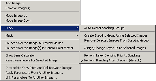
Many of these choices duplicate the functions of the buttons on this screen, but the following items are not accessible via a button:
Stack Menu Items. Images can be assigned a "Stack ID" (and/or a "Layer ID") using the right-click menu on this screen. The stack ID is used by the stacking program, which combines all images with the same Stack ID into a single image. The Layer ID is only used if the "layer blending" option is enabled. See the Processing/Workflow section for more details.
- Auto-Detect Stacking Groups. If selected, PTAssembler assigns stack IDs automatically to selected images by examining the position of each ("Auto-Detect Stacking Groups"). If PTAssembler encounters images that are positioned in the same location (or very close to the same location) then PTAssembler assumes that they ought to be part of a "stack", and assigns them the same Stack ID. Note that PTAssembler's ability to assign images to stacks depends on the yaw, pitch and roll values for those images. Until values for yaw, pitch and roll have been assigned, or the project has been optimized, these parameters all have a value of zero, and PTAssembler will assume that all images belong to the same stack. Because of this, the option to auto-detect stacking groups should only be used after the project has been optimized, and/or values for yaw, pitch and roll have been assigned.
- Create Stacking Group Using Selected Images. PTAssembler assigns an unused stack ID to all selected images.
- Remove Selected Images From Stacking Group. PTAssembler remove selected images from any stack group to which they belong.
- Assign Change Layer ID to Selected Images. Prompts the user to assign/change the layer ID to selected images. Because all images that have a stack ID must also have a layer ID, PTAssembler automatically assigns a layer ID to any image when a stack ID is assigned. You can use this menu option to change the assignment of layer ID to group images into desired layers. The layer ID is only used by PTAssembler if layer blending is enabled. If layer blending is enabled (see below), then all images within the same layer are blended prior to stacking.
- Perform Layer Blending Prior to Stacking. If chosen, the selected images will be "layer blended" before stacking. (See the Processing/Workflow section for more details on layer blending). Note that if any image in a stack is configured to be layer blended, then all images in the stack must be layer blended. PTAssembler will enforce this requirement even if the user does not explicitly specify all images within a stack when clicking this menu option.
- Perform Blending After Stacking (default). If chosen, the selected images will be stacked before blending. This is the default mode of operation for PTAssembler and is recommended for most circumstances.
Mask Menu Items. The "Delete Mask(s)" menu item deletes any masks that are assigned to the selected images.
Interpolate Yaw, Pitch and Roll Between Images... In some cases, the images in your project may not have enough detail (e.g. featureless blue sky) for you (or a control point picker plugin program) to assign control points. In this case you can use PTAssembler's interpolation feature to automatically estimate the correct position (yaw, pitch and roll) parameters based on the position of other images in the project for which the position can be determined by the optimizer. With three or more images selected you can choose to interpolate yaw and/or pitch and/or roll parameters for selected images. Right-click on three or more images and select the "Interpolate Yaw, Pitch and Roll Between Images" menu option to activate this feature. In order for the interpolation algorithm to work, all images that are selected must belong to the same "row" or same "column" in the panorama. This is because the interpolation algorithm assumes that the images that are selected were captured using a consistent (or roughly consistent) pattern so that image-to-image differences in yaw, pitch and roll between images are similar.
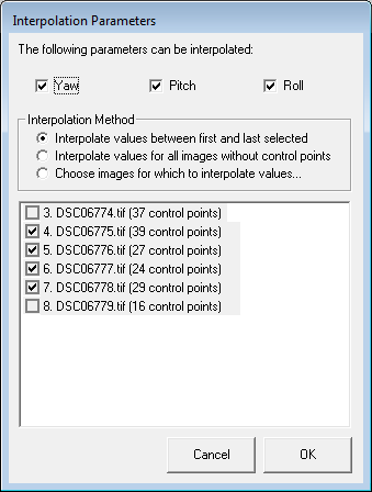
For example, if you capture a sequence of 7 images from left to right and image #3 contains no control points, but is in between image #2 and #4, then you can use this feature to interpolate the yaw value for image #3. Yaw, pitch and/or roll values can be interpolated for multiple images simultaneously, and there are three different interpolation methods. The first method ("Interpolate between first and last selected") will interpolate values for all images selected except for the first and last selected images. The second method ("Interpolate all images without control points") will only create values for images that do not contain any control points. PTAssembler uses the first and last images selected that contain control points as the values between which to interpolate. Note that using this setting the images to be interpolated need not be in between the images that contain control points. The third method ("Choose images for which to interpolate values") allows you to specify the images for which yaw, pitch and/or roll should be interpolated.
Interpolating values from neighboring images is a last-resort solution for determining yaw, pitch and roll for the images in a project. If control points can be identified then this is preferable. However, for projects where this isn't possible, using the interpolation feature can often help assign yaw, pitch and roll for images that would otherwise be difficult to position.
Apply parameters from another project... This is same feature as described in the Tools menu.
Link Parameters to Another Image... Prompts the user to select another image in the project to which parameters for the selected image should be linked. If linked to another image, the parameter values for the selected image are set equal to the other image whenever the project is optimized. The linked parameters are the position (yaw, pitch, roll) and lens (a, b, c, d, e, g, t, fov) parameters.
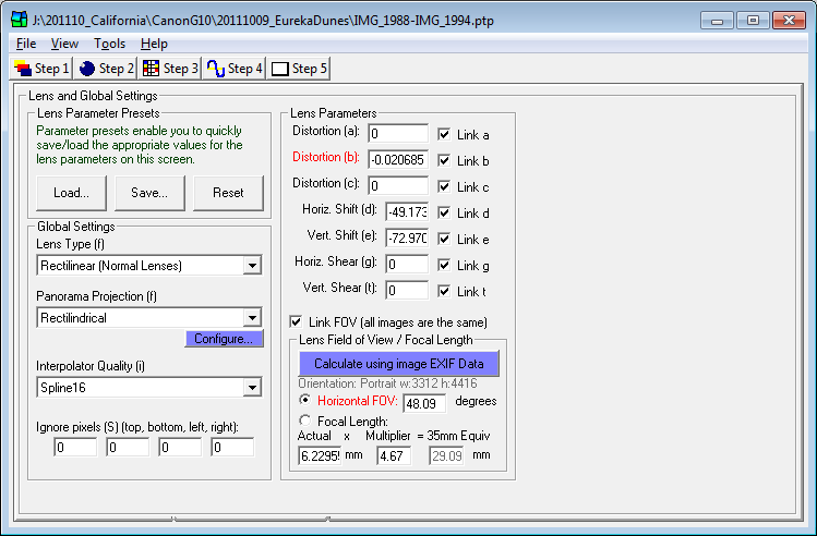
This screen contains several fields that describe your camera lens ('Lens Parameters'), as well as several options that control the final panorama. Brief descriptions of all controls on this screen are as follows:
- Lens Parameter Presets. These buttons enable you to load or save the lens settings on this screen as a 'preset'. For more information, see the Lens Presets Screen.
- Global Settings.
- Lens Type. Choose the type of lens that your camera uses. If in doubt, choose 'rectilinear'.
- Panorama Projection. This determines the mapping or projection used by the final panorama. If in doubt, cylindrical or rectilinear projection are usually best.
- Interpolator Quality. To create a stitched image, the stitching engine must remap the images so that they line up correctly. During this remapping, one of several different interpolators can be employed. Using a higher quality interpolator produces better results but takes longer. The available interpolators vary between stitching programs (e.g. PTAStitcher vs PTMender), but they are listed in approximate order of quality with the highest quality (and slowest) interpolators towards the bottom of the list. In general, even the low quality interpolators produce very good results. Rapidly diminishing marginal quality improvements set in very quickly after the first couple of options on this list, so there is usually no need to employ the highest quality, slowest interpolators.
- Ignore Pixels. You can instruct the stitching engine to ignore a border around your images by entering values here.
- Lens Parameters. By default, all lens parameters are 'linked'. This means that all images in your
project have the same lens parameter values. In some cases, however, you may wish to 'unlink' the parameters
so that different images can have different values. If parameters are 'unlinked', you may enter their values
on the Step 1 screen and optimize their values on the Step 4 screen. (You
may also link parameter values for groups of images using the Step 4 screen.)
- Distortion (a,b,c). These values describe the distortion in your lens. Very few lenses are perfect, and most produce images with some (usually slight) distortion, usually visible as a slight curvature along straight edges. You can estimate appropriate values for these parameters using the optimizer. (The b parameter is red because it is usually the most important...it is often the case that a lens' distortion can be completely described using the b parameter only).
- Horizontal and vertical shift (d,e). These values specify the horizontal and vertical offset of the camera/lens measured in pixels. You can estimate appropriate values for these parameters using the optimizer. For most images, these values are usually zero.
- Horizontal and vertical shear (g,t). These values are useful for images created with slide and transparency scanners where there is some slight misalignment of the scanner relative to the film resulting in this type of distortion. You can estimate appropriate values for these parameters using the optimizer. For most other images, these values are usually zero.
- Lens Field of View/Focal Length. The optimizer and stitching engine need to know the horizontal
(i.e. left-to-right) field-of-view (angular coverage) of your lens. This is the only parameter on this
screen that must be entered (hence it is marked in red). Note that the lens field of view changes
depending on whether the image was taken in portrait or landscape orientation. If you know or can compute this
value, you should enter it here. If you don't know the field-of-view for your lens, PTAssembler can help you
compute it using information about the lens' focal length as follows:
- Actual Focal Length. If you do not know the field-of-view, you can enter the lens' focal length instead, and PTAssembler will compute the field-of-view for you. Note that PTAssembler has to take into account the width/height of your image in order to compute a field of view from the focal length. The values that PTAssembler assumes for the width and height are calculated by examining the first image in the project, and are displayed in light gray text just above the 'Horizontal FOV' box.
- Multiplier. If you are not using a 35mm film camera or a "full-frame" digital SLR camera, then you will need to enter a multiplier value (other than the default value of 1) in order to convert the actual focal length of your camera to its '35mm equivalent value'. The actual focal length is usually marked on the camera's lens. Many consumer-level digital cameras, for example, have very short focal lengths. For example, a typical 3x zoom consumer digital camera might have an actual focal length of about 7-21mm. However, because of the small (relative to the size of a 35mm film negative) sensors in consumer level digital cameras, their short focal length lenses give the same field of view (angular coverage) as longer focal length lenses attached to a 35mm camera. For example, if the 7-21mm digital camera lens gives the same field-of-view as a 35-105mm lens on a 35mm camera, then the the appropriate multiplier is 5 (7-21mm multiplied by 5 equals 35-105mm). Most manufacturers report either the focal length multiplier or 35mm equivalent focal length for the digital cameras they make. In some cases, PTAssembler can calculate this value automatically, if your camera includes enough information in the EXIF data it records (see below....some do, some don't).
- EXIF Data. Most digital camera images store EXIF data inside the images they produce. This data often records information about focal length, and sometimes records enough information so that PTAssembler can determine the appropriate multiplier. If your images contain EXIF data, you will see a button called "Calculate using image EXIF data". Clicking this button causes PTAssembler to extract focal length and/or multiplier information from your image and compute the horizontal field of view. See also the "misc" tab of the preferences screen for more information about how to enter a default multiplier value to be used if the EXIF data in your images do not contain multiplier information.
- (PTStitcher only) Color/Brightness Correction. If the color and/or brightness of your source images vary, you can use this feature to correct the images when stitching. You must choose one 'reference image' in which the color/brightness is not changed. You can choose either the reference image that is set on Step 3 or a specific image number (images are numbered starting at 1). Note that this feature of Panorama Tools may not work correctly for all images. In some cases it can produce areas of incorrect color, and is far less reliable and effective than PTAssembler's photometric adjustments. It is recommended that you always use the same exposure (aperture, shutter speed, ISO setting) and whitebalance when capturing images for the most consistent results. Normally, no color or brightness adjustment is needed if the exposure and whitebalance settings are kept constant for all exposures. Note: PTStitcher supports color/brightness correction, but PTMender does not.
- (PTStitcher only) Morph-to-fit options. Use this feature to access Panorama Tools' morph-to-fit capability. In addition to morphing all control points, you can also choose to morph selected control points (that are selected on the Step 4 screen).
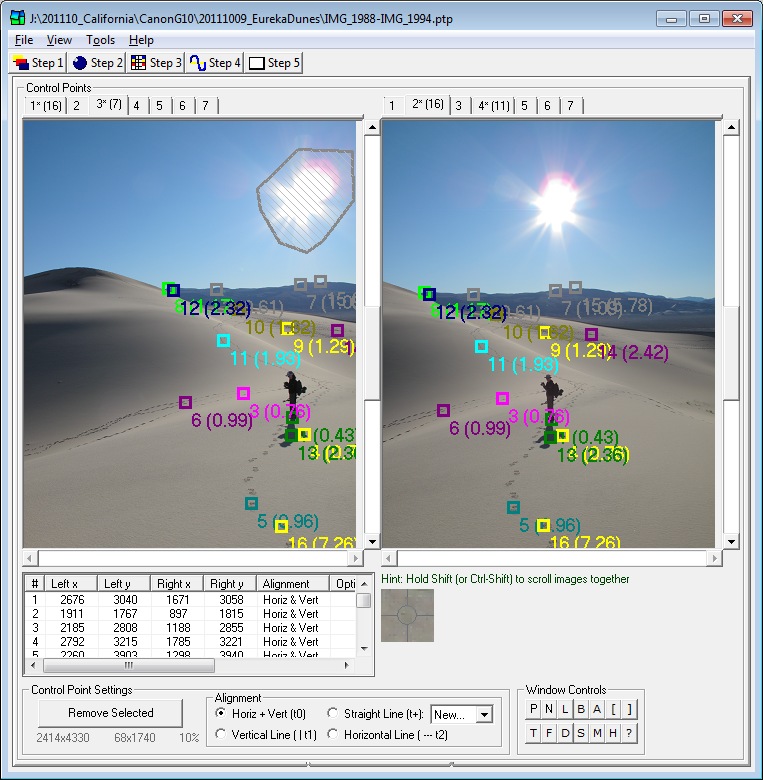
This screen allows you to create "control points" (and "mask regions"...see below) on your images. Because these control points are used by the optimizer to determine how your images should be aligned, the more careful and precise you are, the better your final results will be. Any feature (e.g. a brick, tree, leaf, door handle, etc.) that appears in both images (i.e. in the overlap region) can be used as a control point. You should try to select about 5-8 control points for each pair of adjacent images. Selecting more than this amount probably won't produce better results. In fact, it will slow the rate at which the optimizer works and make it more difficult to detect misplaced control points.
Clicking once in one of the viewers sets a temporary marker and a small magnified "zoom" window appears to indicate precisely where you clicked. Clicking in the other viewer window completes the creation of the control point. If selected on the preferences screen, the cursor will automatically move into the other viewer after the temporary marker has been placed, if PTAssembler can make a reasonable guess as to the approximate location of the matching control point. (PTAssembler needs one control point to have already been set for an image pair in order for this feature to work).
The images can be scrolled using the scroll bars or the middle wheel of the mouse (if available). Hold the mouse over the image you want to scroll, and move the mouse wheel. By default, the mousewheel scrolls images vertically when the images viewers are displayed side-by-side, and horizontally when the image viewers are displayed top-to-bottom (See keyboard shortcut "T" in this section), but the scroll direction can be toggled by clicking the middle mouse button (typically the same as clicking the scroll wheel). Holding the shift key down while scrolling will cause both images to scroll at the same time.
Clicking on the numbered tabs at the top of the screen loads the corresponding images into the viewer windows. If more than 250 images are added to the project, "next" and/or "prev" tabs will be displayed to navigate to higher and/or lower numbered images in the project. The numbered tabs also indicate other images that share control points with the currently loaded image (denoted by an asterisk) and the number of shared control points between images (indicated by a number in parentheses).
The viewer windows display any control points that have been added to the project. (The shape and size of the control point indicators can be changed on the preferences screen). The following indicators may also be displayed next to the control point:
- Control point number/optimizer distance. A number that identifies the control point is displayed to the right and below the control point. The optimized distance (if calculated) is displayed in parentheses.
- Control point alignment. The control point alignment (e.g. horizontal, vertical or line) is displayed to the right and above the control point.
- Morph-to-fit code. If the project is using morph-to-fit for selected control points (See Step 2 screen), and this control point has been selected for morphing, a small 'M' is displayed above and to the left of the control point.
- Micro-position distance. If PTAssembler has "micro-positioned" (See preferences) the control point, the amount that it has been adjusted is displayed next to the control point.
Clicking on the image viewers does the following:
- Create Control Point (Left Click). Left clicking in one viewer will place a small circle on the image to indicate where the mouse was clicked. Left clicking in the other viewer will then cause a control point to be added to the project.
- Create Multiple Control Points (Left Click and Drag). Holding the left mouse button down while dragging will cause a temporary line to be drawn on the image. Doing the same in the other viewer will draw a similar temporary line. When the mouse button is released, the two lines are converted into control points at regular distances (specified on the preferences screen). This is a quick way of adding several control points to a project without repeated clicking.
- Create Mask Region. (Ctrl key and Alt key and Left Click). Clicking the mouse while holding the ctrl and alt keys down can be used to define "mask regions" on the image. See below for a detailed explanation of mask regions.
- Increase Zoom. (Alt Key and Left Click). Clicking the mouse while holding the alt key down will magnify the images displayed in the viewer windows (up to a maximum magnification of 100%), recenter the images around the clicked point, and place the mouse cursor over the clicked point.
- Reduce Zoom. (Ctrl key and Left Click). Clicking the mouse while holding the ctrl key down will reduce the magnification of the images displayed in the viewer windows (down to a minimum of 1% magnification), recenter the images around the clicked point, and place the mouse cursor over the clicked point.
- Show Control Point Options. (Right Click on a control point). This displays a popup menu with options to delete, move, micro-position (See preferences), or change the alignment of a control point. There are also options to specify whether the control point is to be used for the morph-to-fit feature (see the Step 2 screen), and/or whether it should be used by the optimizer (See the Step 4 screen).
- Show General Options. (Right Click in an empty region). This displays a popup menu with several screen options (e.g. load next two images, maximize viewer area, swap images, toggle splitter orientation, etc.).
- Delete Control Points. (Right Click and drag). Holding the right mouse button down while dragging will cause a temporary rectangle to be drawn on the viewer window. When the mouse button is released, any control points that fall inside the rectangle are deleted.
- Create Control Points in Region. (Shift Key and Right Click and Drag). Holding the shift key down, and dragging the mouse while pressing the right mouse button causes a temporary rectangle to be drawn on the viewer window. Keeping the shift key pressed, and dragging the mouse while pressing the right mouse button in the opposite viewer window causes a temporary rectangle to be drawn in the opposite viewer. When the right mouse button is relased, PTAssembler invokes PTAPicker to detect control points in the regions marked by the temporary rectangles. A temporary rectangle must be visible in each viewer before control points can be detected. Note that this feature only works if PTAPicker is selected as the control point picker program.
- Scroll Options. (Middle Click). Toggles the direction that the mouse scroll wheel controls when scrolling images in viewers.
Holding the shift key down while scrolling either of the two viewers (using the vertical or horizontal scroll bars) will cause the opposite viewer to scroll in the same direction. Holding the control and shift key down while scrolling will also cause both viewer windows to scroll together, but will also reset the relative positions of the two viewer windows.
Beneath the left image viewer is table that displays information about all the control points added to the currently displayed images. Clicking on a column header will sort the table. Clicking on a row in the table will scroll the images in the viewer windows to bring the control point into display, and the control marker is temporarily highlighted. Note: To display information about all control points in the project, use the Control Point Information Screen, by clicking on the Show all Control Points menu item.
A zoom window (that shows an enlarged portion of the image directly underneath the mouse cursor) is displayed beneath the right image viewer. (An option to 'undock' the zoom window can be found on the preferences screen).
Control Point Settings are displayed at the bottom of the screen, and can be used to remove a control point or set the alignment code for newly added control points.
Mask Regions. A secondary purpose of this screen is to allow for the creation, display and manipulation of "mask regions". A mask region defines a region of the image that is "masked" and ignored by the stitching program (PTAStitcher only). As a result, any region that is masked in the input image produces a blank/empty region in the output image produced by the stitcher. This is useful if an image contains an object that you explicitly want to exclude from the final result. For example, if a person appears in the overlap region between two images, but the person has moved between images, you may wish to draw a mask region around the person in one image to ensure that they only appear once in the final result.A mask region is created by drawing a polygonal shape on the image. A polygon is an arbitrary shape defined by three or more user created points. To create a mask region, click on either of the images while holding the "Alt" and "Ctrl" keys pressed. Each click will add a new point to the image (indicated by a small red circle). To complete the polygon, you can either click the first created point in the polygon, or double click (keeping the Alt and Ctrl keys pressed) and the Polygon will be complete. The interior of the mask region is indicated with a series of diagonal lines.
After a mask region has been created, you can delete it by right clicking inside it, and a popup menu will appear with a choice to delete the region. Similarly, a mask region can be inverted by right clicking inside a region and selecting the menu choice to invert the region. If you only want to include a small portion of a particular image, it can be more efficient to define a mask region containing the region you want to include, and then inverting the region. After the region has been inverted everything except the region you want to include will be masked.
A mask can also be copied to all other images in the project by right clicking inside the mask and selecting the "Copy Mask Region to All Images" from the Mask popup menu.
Keyboard Controls. There are several keyboard controls available on this screen, some of which can also be accessed using the "Windows Control" buttons at the bottom of this screen.
- P Increments the images shown in both viewers by one. (Keyboard shortcut: p)
- N Decrements the images shown in both viewers by one. (Keyboard shortcut: n)
- T Toggles the orientation of the splitter bar between vertical and horizontal. (Keyboard shortcut: t)
- F Maximizes the size of the viewer windows, temporarily hiding all other controls on screen. (Keyboard shortcut: f)
- L Increases the brightness/contrast of the image in the zoom window. (Keyboard shortcut: l)
- D Decreases the brightness/contrast of the image in the zoom window. (Keyboard shortcut: d)
- B Tries to reposition the images inside the viewer windows to show control points. (Keyboard shortcut: b)
- S Swaps the left and right images. (Keyboard shortcut: s)
- A Runs the contro point picker program (see plugins tab of preferences screen) and creates control points for currently visible images. (Keyboard shortcut: a)
- M Micro-positions (See preferences) all control points on currently displayed images (Keyboard shortcut: m)
- H Thins control points. Limits the number of control points to the amount specified on the (See Control Point Information) screen, by removing surplus control points with highest control point distance. (Keyboard shortcut: h)
- [ Decreases the magnification of the viewer windows.
- ] Increases the magnification of the viewer windows.
- Shift [ Resizes the images to fit to viewer windows.
- Shift ] Resizes the images to 100%.
Additional keyboard controls are as follows:
- q Toggles the most recently placed control point between its original and micro-positioned location.
- Arrow keys Move cursor left/right/up/down one pixel at a time.
- Enter key Simulates a left mouse click (i.e. sets a control point).
- +/- keys Increase/decrease the zoom amount in the zoom window.
- Right Mouse keyboard button Simulates a right mouse click (i.e. displays popup menu).
- Shift and 'n' key Increments the image shown in the left viewer, and decrements the image shown in the right viewer.
- Shift and 'p' key Decrements the image shown in the left viewer, and increments the image shown in the right viewer.
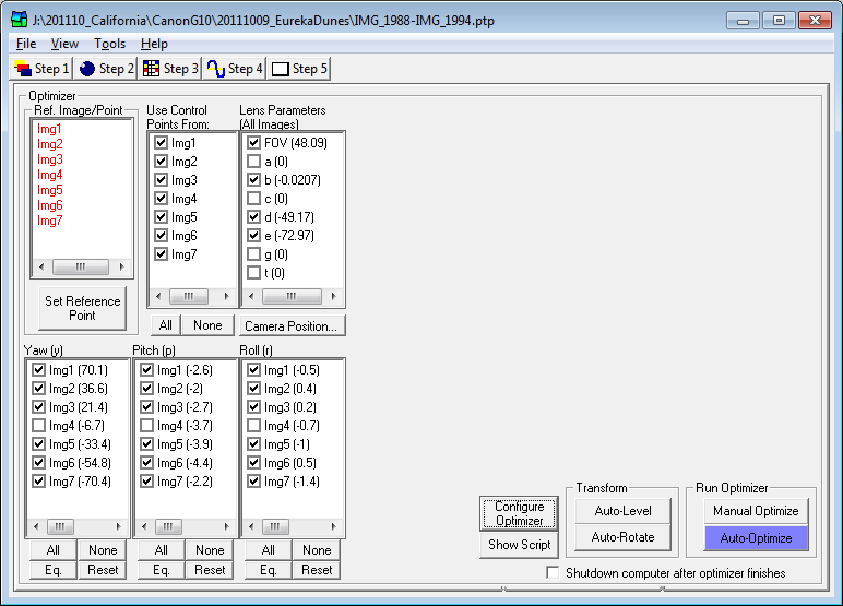
This screen allows you to run the "optimizer". By using the control points set on the Step 3 screen, the optimizer calculates appropriate values for position (i.e. yaw, pitch, roll) and/or lens parameters for your images. These values are necessary so that the stitching engine knows how to warp and align the images to create your final stitched image.
Reference Image. By clicking on one of the red image numbers in the 'reference point' frame, you can choose a reference image. This is an image for which the yaw, pitch and roll parameters are not optimized. It is a good idea to select a reference image because if yaw, pitch and/or roll parameters are optimized for every image in the project, then there is no unique "best fit" solution for these parameters. A simple analogy may help illustrate this important concept: If you know that x+y=5 and that x=2, then you can calculate that y=3. However, if you don't know that x=2, then there is no way of knowing the value for y. Similarly, without a reference image (i.e. "x=2"), the optimizer can't determine the correct value for the other images. Note that one can manually select the images for which yaw, pitch and roll should not be optimized by manually unchecking the desired check-boxes for yaw, pitch and roll. In this case, it is not necessary to select a reference image. (Also, if you have added vertical and/or horizontal line control points to the project, then these line points may give enough positioning information to the optimizer so that yaw, pitch and/or roll may be optimized for all images. For more information on horizontal/vertical line control points, and optimizing manually, please consult the links in the Links and more reading section below.)
Reference Point. Once you have selected a reference image, you may also select a reference point. Clicking the 'Set Reference Point' button will show the reference image in the Reference Point Picker Screen and enable you to choose a reference point. The reference point is useful for determining the exact positioning of the panorama. The reference point becomes the center point (before any cropping is performed) of the final output image. It is not necessary to select a reference point, however, because one can also adjust the position of the panorama using the preview screen after the project has been optimized.
"Use Control Points From" checkboxes. Use this checkboxes to control which images are used when running the optimizer. By default, all checkboxes are checked. However, if an image is unchecked, any control points that use this image are not used when the optimizer is run.
Lens Parameters checkboxes. Use this box to determine which lens parameters should be estimated by the optimizer. The current value for a parameter is displayed in parentheses. If any of the lens parameters are unlinked (See Step 2 screen), individual lens parameter lists are displayed (one list for each unlinked parameter) on the right half of this screen where you can select the individual images for which these parameters are optimized.
Yaw, Pitch, Roll checkboxes. Use these boxes to select the images for which the yaw, pitch and roll parameters should be estimated by the optimizer. If checked, the optimizer will estimate the parameter value. The 'all' and 'none' buttons quickly check or uncheck all images in a box. The 'Eq' (equalize) button will adjust all the parameter values so that they are centered around 0 (useful for quickly correcting an image that is off-center). The Reset button will reset all parameter values to zero except for the value for the reference image (if a reference image has been selected).
Right Click Options Right clicking on one or more entries in the lens parameter or yaw, pitch and roll list boxes will bring up a menu that allows you perform several addition functions:
- Check/Uncheck. These menu items allow you to check or uncheck the boxes for the selected parameter(s). If you want to check or uncheck multiple values, it is quicker to use the menu, than check/uncheck each box individually.
- Modify Values... This menu item allows access to a dialog that allows you to modify the values for the selected parameter(s). A new value can be specified that can either (1) replace the existing value or (2) be added to the existing value. The second option is useful for modifying the value of multiple images by the same amount (e.g. shifting the pitch for all images by 2 degrees or moving all images in the project by 3 degrees to the left). Note that parameter values can also be modified using the Step 2 screen, but may be more convenient for some users on this screen.
- Link/Unlink... This menu item allows access to a dialog
that allows you to "link" the parameter value of one or more ("target")
images to another ("source") image during optimization. Yaw, Pitch and Roll parameters
for individual images can be linked to another image. Similarly, lens parameters
(e.g. a, b, c, FOV, etc.) for individual images can be linked another image, as long as
these parameters are first "unlinked" on the Step 2 screen.
For example, you could link the FOV ("Field of View") parameter for images 2 and 3 to image 1, and link the FOV for images 5 and 6 to image 4. During optimization the FOV for images 2 and 3 would be assigned the same value as the FOV for image 1 and the values for images 5 and 6 would be assigned the same value as the FOV for image 4. In this example image 1 is called the "source" image, and image 2 and 3 are called the "target" images. Similarly, image 4 is the "source" image for images 5 and 6 ("target" images). This feature is useful if some images in the project were taken with one setting (e.g. focal length/FOV), and another set of images were taken with another lens settings (e.g. focal length/FOV).
If an image is linked to another, then the number of the source image to which the target image is linked is displayed next to the target image in square brackets. For example, this text indicates that image 2 (target image) currently has a value of 50.0, but linked to image 1 (source image), so that whenever the project is optimized, the parameter value for image 2 will be set equal to the optimized value for image 1.
Img2 (50.0) [=1]
Camera Position... button. Clicking this button shows the Camera Parameter Position screen. The color of the button changes depending on the camera position parameters as follows:
- Grey: All camera position parameters are zero, and none are checked to be optimized
- Blue: All camera position parameters are zero, but some are checked to be optimized
- Red: Some camera position parameters are non-zero, but none are checked to be optimized
- Green: Some camera position parameters are non-zero, and some are checked to be optimized
Show Script button. Clicking this button will show the script that PTAssembler creates and sends to the optimizer. You can manually edit this before clicking the optimize button if you wish.
Configure Optimizer button. This button brings up a dialog where several optimizer settings can be configured. These options are described in detail here. (Not present when using PTOptimizer).
Manual Optimize button. Clicking this button will run the optimizer, and display the results. You will be prompted to accept or reject the optimized values created by the optimizer. See the Links and More Reading for information on how to optimize manually. Although it is usually easier to use the "Auto-optimize" button (see below), manually optimizing using the "optimize" button allows more control over the optimized result. This is the most reliable way to achieve the desired results.
Auto-Optimize button. Optimizing variables is often best done in steps...optimize some variables, accept the results and then optimize again using a different (usually larger) combination of variables and images. PTAssembler's 'Auto-optimizer' automates this multiple-step process by running the optimizer several times in rapid succession. The Auto-optimizer also takes care of deciding the order in which parameters and images are optimized. In most cases, the auto-optimizer will generate the correct results, although in some cases you may wish to optimize manually (i.e. selecting parameters and clicking the optimize button). See above for instructions on using the manual "Optimize" button. See the bottom of this document for links to web resources that explain the art of optimizing in more detail. A good grasp of the concepts behind the optimization process is helpful for making good choices about what and when to optimize.
The "Auto-optimize" button follows a sequence of optimization steps that can be configured using the Preferences screen. In some cases (depending on the image ordering, lens type, and artistic intent) the steps may not be appropriate. You may want to reconfigure the auto-optimizer using the Preferences screen, and/or optimize manually. Please consult that section for more information about how and what the auto-optimize feature chooses to optimize.
When the auto-optimizer has finished running, a dialog is presented that displays that the results of the optimizer and information about how well the images can be joined together to create a final panorama/mosaic. The dialog prompts the user to create a "preview" image (i.e. a small-scale version of the final image). (Advanced hint: If PTAssembler is not configured to use its own internal preview viewer/editor, it will "auto-size" the parameters on the Step 5 Screen before creating a preview image. However, if you hold the shift key down while clicking "Yes" in this dialog, PTAssembler will not modify any of the parameters on the Step 5 Screen before creating a preview image).
Cancel Optimize button. This button is only visible while the optimizer is running. If pushed, the optimizer will stop executing and return the results of its most recent iteration. (Not present when using PTOptimizer).
Auto-Level button. The Auto-Level button tries to level the horizon. It does this by determining the pitch for each image in the project that minimizes the distribution of roll parameters. Using this feature will change the vertical positioning (i.e. pitch) of the reference point. This button can be helpful in correcting a "bowed horizon", due to incorrect placement of the reference point. Note that this feature performs the same operation as the the "correct pitch" button on the preview viewer/editor screen.
Note: Because this feature relies upon examining the distribution of the roll parameter, an underlying assumption is that all images should all have the same (or very similar) roll. Luckily, all images should have the same roll if they were taken using a tripod with a pan head or a panoramic/spherical head. If the images were taken hand held, then some degree of variability in the roll parameter is normal, and this feature will probably not work as described above (unless you have an extremely steady hand and are a very good judge of level!). So, if you didn't use a tripod when capturing your images, this feature may not work as well...or at all.
Here is a more detailed explanation of this feature: There is usually a pattern to the way in which yaw, pitch and roll parameters are distributed in a project. Typically, if the pitch parameter has been incorrectly specified for the reference image, the roll parameter for each image is correlated with its yaw position. For example, if the pitch parameter has been set too low (i.e. a reference point is set too high), the roll parameters for images at the left of the image will be consistently less than the roll parameters for images at the right edge of the image. If you choose cylindrical output projection, this will also produce a "curved" horizon. The Auto-level feature tests different pitch values for the reference image until it settles on a pitch value that removes (or removes as much as possible) the correlation between roll and yaw for each image.
Auto-rotate button.This feature attempts to rotate all images and to ensure maximum usable vertical area in the final image. This is similar to the auto-level feature, but rather than adjusting the pitch for each image, this adjusts the roll for each image. It is useful for projects where the camera might not have been level when rotating left/right and the images appear to slope up/down when moving from left to right.
This feature analyzes the pitch for each image in a project and then calculates what adjustment to the roll parameter for all images would ensure the maximum usable vertical area. Usable vertical area is defined as area that is not empty due to a missing image, or region into which no input image can be mapped. Note that because this feature relies upon differences in the pitch parameter for each image to compute the appropriate roll adjustment, it will not work if all values for pitch are still at their default value of zero. Note that this feature performs the same operation as the the "correct roll" button on the preview viewer/editor screen.
Shutdown checkbox. If the 'Shutdown computer after auto-optimizer finishes' box is checked, PTAssembler will attempt to shut down and poweroff the computer when the optimizer has finished processing. (This feature may not work on some older computers that lack the ability to be shutdown from a software command.)
The appearance and behavior of some features on this screen changes slightly depending on whether PTAssembler is configured (via the preferences screen) to use its own internal preview viewer/editor or an external preview application. If PTAssembler is configured to use an external preview application, values for horizontal field of view, preview width and preview height must be specified on this screen before a preview is created. These can be specified manually by entering values into the appropriate boxes, or PTAssembler can populate these fields with reasonable values if the "Auto Size Parameters" button is clicked. When the preview button is pressed, PTAssembler instructs stitching engine to create a small-scale JPEG version of the project, and immediately launches it using the preview viewer. No adjustments or changes to the project can be made via an external preview application, so it is recommended to use the internal preview viewer/editor for most flexibility.
If PTAssembler is configured to use its own internal preview viewer/editor, then there are no entry boxes for preview width and preview height (these are computed automatically by PTAssembler). By default, when using the internal preview viewer, the value selected in the horizontal FOV box is ignored, and automatically adjusted to a value just large enough to encompass all input images. However, if the shift key is depressed while the preview button is clicked, then PTAssembler will not adjust the FOV. Rather, PTAssembler will use the value in the FOV box unless it is mathematically impossible (e.g. a rectilinear panorama with a field of view greater than 180 degrees), in which case PTAssembler will recalculate an appropriate FOV value.
Creating a preview image is not strictly necessary, but is extremely useful for checking your image before producing a full sized image (which may take several minutes depending on the size of the project and the speed of your computer). In addition, using PTAssembler's internal preview viewer/editor allows you to adjust the positioning, field of view and projection of the project, seeing the results of these adjustments immediately. Note that the preview only performs the stitching/remapping process of the processing workflow, and does not perform any other processes such as pre-processing, blending, stacking, etc. This enables PTAssembler to generate a preview as quickly as possible, but may result in some seams being visible in the preview that will not be visible in the final image. Similarly, the preview step does not use morph-to-fit (see Step 2 screen).
When creating a final (full-size) image, values for width and height of the final image must be specified, and the horizontal field of view for the output image must be specified. The Auto-Size Parameters button can be used to populate these fields with values. However, if PTAssembler's internal preview viewer/editor is used, then these values will be automatically populated by the internal preview viewer/editor when it is closed.
In short, if you are using PTAssembler's internal preview viewer/editor screen to create a preview, then you should not need to adjust the width, height or FOV fields on this screen under normal circumstances.
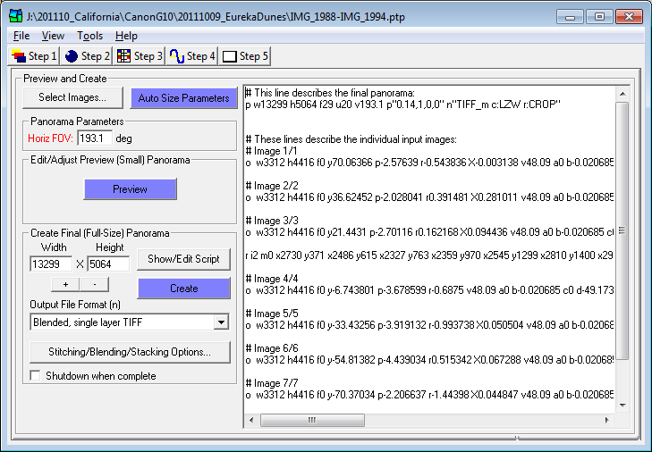
Select Images... Shows a dialog where you can choose to include/exclude any combination of images from the final stitched image. Any images that are excluded on this screen remain part of the PTAssembler project file, but are excluded from any stitching. By default, all images in the project are included.
Auto Size Parameters. The 'Auto Size Parameters' button fills in the 'width', 'height' and 'Horizontal FOV' boxes with appropriate values that are computed based on the images in your project. These are 'best-guess' values, but may need to be manually adjusted depending on your desired results.
Panorama Parameters: Horizontal FOV. The 'Horizontal FOV' box allows you to specify the horizontal field-of-view (i.e. left-to-right angular coverage) for the final image. If set too large, your final image will have extra empty 'black-space' at the edges. If set too small, your final image will be cropped at the left and right edges. You can use the 'Auto Size Parameters' button to have PTAssembler fill in this field with an estimate. Also, see the explanation for the '+/-' buttons.
Panorama Parameters: Feather Width The 'Feather Width' box allows you to specify the width of the blending region between images (only applicable for some output file formats such as JPG, Multiple TIFF with masks, layered Photoshop with masks, etc.).
Width/Height. The 'Width' and 'height' boxes allow you to specify in pixels the size of the preview and final images that should be created by the stitching engine. You can use the 'Auto Size Parameters' button to have PTAssembler fill in these fields with an estimate. (See note about size for more details, and some qualifications).
+/-. The '+' and '-' buttons allow you to increase or decrease the width and height values for the final and preview images in small increments. Advanced hint: If you hold the shift key down while clicking the '+' and '-' buttons, the Horizontal FOV will also be adjusted as well as the width and height. This is useful if you want to increase/decrease the amount of 'black-space' around the final image without significantly affecting the size of the actual usable image. In other words, you use this technique to adjust the 'tightness' with which the final image is cropped. (See note about size for more details, and some qualifications)
Output File Format. The 'Output File Format' box allows you to select the file format for the final image. The following file formats are available when using (the default) PTAStitcher as the stitching engine (file formats for PTStitcher/PTMender may differ):
- Multi-layer PSD w/ masks
- Multi-layer PSD no masks
- Single layer JPEG
- Single layer PSD
- Single layer TIFF
- Multiple image TIFF
- Multiple image TIFF w/ masks
- Blended, single layer TIFF
- Single layer PSB
- Multi-layer PSB w/ masks
- Multi-layer PSB no masks
For best results, the "Blended, single layer TIFF" format is recommended.
When this option is chosen, multiple TIFF files are produced by
the stitching/remapping process, and PTAssembler then invokes a blending program (i.e. Enblend, Smartblend or Multiblend)
with the images produced by the stitching/remapping process. See the
section on Workflow for more details. Using Blended
TIFF output also allows for the use of the stacking and cropping
processes, if desired.
All of the "Single layer" formats (JPG, PSD, PSB, TIFF) produce images where a
fast rudimentary seam blending between adjacent images has been performed by the stitching engine.<
The "Multi-layer" formats (PSD and PSB) produce a single image with
multiple layers...one layer for each input image. These formats can be opened in Photoshop, and allow the user
to manually blend the layers to create a final flattened output. PSB can handle
files larger than 2GB in size, while PSD cannot (although PSB is only compatible
with newer versions of Photoshop). The options "with masks", add a mask channel
to each image layer where black space around the image data is masked.
The "Multiple image" TIFF formats are similar to the "Multi-layer" formats,
except that the individual layers are output as individual files...one output file for
each input file. These files can be used as input to automated blending programs (e.g. Enblend/Smartblend/Multiblend),
or imported into other editing programs (e.g. the GIMP) where the layers
can be manually blended. The "Multiple image" formats also allows for the
stacking process to be executed, because the stacking programs
require multiple images as input.
Preview and Create. Clicking the 'Preview' or 'Create' buttons will start the creation of a preview or final image. (Holding the shift key while pressing preview will prevent PTAssembler from trying to adjust the FOV, width and height based on the current input image sizes/positions, and PTAssembler will use whatever is currently entered on this screen.) The preview image is designed to show the relative position of images in a project, and to generate as quickly as possible, so it only remaps the images to their final position in the panorama, and does not perform any other processing like blending or stacking. The final image (generated by clicking the 'Create' button) performs any blending, stacking or other processing requested on the processing options screen.
Show/Edit Script. Clicking the 'Show/Edit Script' buttons allows you to view and/or modify the script created by PTAssembler before it is used by the stitcher program. If you want to edit the script before launching the stitcher program, do no hide the script before clicking the "Create" or "Preview" button, otherwise PTAssembler will overwrite any changes you might have made with a newly generated script.
Stitching/Blending/Stacking Options... Shows the Processing Options screen where processing can be configured.
Shutdown. If the 'Shutdown computer when complete' box is checked, PTAssembler will attempt to shut down and poweroff the computer when the project has finished processing. (This feature may not work on some older computers that lack the ability to be shutdown from a software command.)
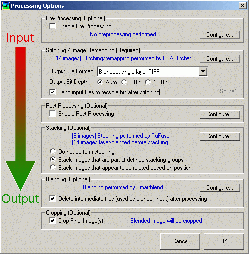
Processing options screen.
Note: Please consult the section on workflow for background information and concepts important to the understanding of this screen.
Pre-Processing. If checked, PTAssembler will run the selected pre-processing command on each image in the project before starting the stitching process. Click the configure button to open the preferences screen where the pre-processing program and its options can be configured. Pre-processing never overwrites the original images, but rather creates temporary files which are used by the stitching process, and deleted once the project has finished executing.
Stitching / Image Remapping. Use this frame to select the format of the image files output by the stitching program. Click the configure button to open the preferences screen where the stitching program can be specified. The output format can also be configured on this screen. File formats are described in detail as part of the Step 5 screen.
The output bit depth options allow you can choose the preferred output bit depth. If "Auto" is specified then PTAssembler will match the output bit depth to the input bit depth. If a project contains images with multiple bit depths (i.e. some images are 8 bit, while others are 16 bit) then PTAssembler will use the higher value. Note, however, that while some formats can support 16 bit output (e.g. TIFF, PSD, PSB), other formats cannot (e.g. JPEG).
If the "Sent input files to recycle bin after stitching" option is checked, the input files will be moved to the recycle bin after the project completes processing.
In the bottom right corner of this frame, the currently selected interpolator (see step 2) is displayed in light grey text. If anti-aliasing (see preferences) is enabled, this is denoted with the letters "aa" in parentheses.
Post-Processing. If checked, PTAssembler will launch a user-defined process when the stitching engine has finished processing. The process is configured using the "configure" button. If you are producing blended TIFF output, then whatever post processing you perform must overwrite the files that the stitcher has created because PTAssembler is not be able to determine if your post processing has created new files with different names, and would not be able to use those when launching the blending process.
The process can be any executable program and PTAssembler allows the
substitution of variables such as the project width/height and output filename
into the command that is executed. For example, if you
want to launch the image output by the stitcher in Internet Explorer when the
stitcher has finished running, you could use a command like this (modify as needed):
"C:\Program Files\Internet Explorer\iexplore.exe" %f
More complex post-processing can be achieved using command-line image editing
programs such as Image Magick.
Stacking. If selected, PTAssembler will launch the stacking program to create single images from each "stack" of images. PTAssembler offers two methods for working with stacks of images:
- Stack Images that are part of defined stacking groups. PTAssembler will stack only those images that are part of defined stacking groups (i.e. they have the same Stack ID on the Step 1 Screen). Images with the same Stack ID are then stacked into a single image using the stacking program.
- Stack Images that appear to be related based on position. PTAssembler will assign Stack IDs automatically by examining the position of each image in the project. If the images are positioned in the same location (or very close to the same location) then they are assumed to be part of a "stack", and are assigned the same Stack ID. Images with the same Stack ID are then stacked into a single image using the stacking program.
This frame also displays the number of images that will be used as input to the stacking program. In general, this is the same number of images that are produced by the stitching program. However, if layer blending (see workflow section) is enabled, then the number of images that will stacked will be smaller, because some of the images produced by the stitching program will have already been blended together prior to stacking.
Blending. If selected, PTAssembler will invoke a blending program (e.g. Enblend, Smartblend or Multiblend) to blend images into one composite after the remapping process (performed by PTAStitcher) is complete. The blending program is used to hide any evidence of a seam between adjacent images that might result from less-than-perfect image alignment, lighting shifts, etc.
If the "Delete intermediate files..." box is checked, then any intermediate files (e.g. those produced by the stitcher and fed to the blender) will be removed after the project finishes processing. These files are either deleted or moved to the recycle bin depending on the preferences.
cropping. If selected, PTAssembler will crop the image output by the blending program to remove any extra "black-space" from around the edge of the image. Note that this option is also configurable via the preferences screen. See A Note About Output Size for more information about cropping.
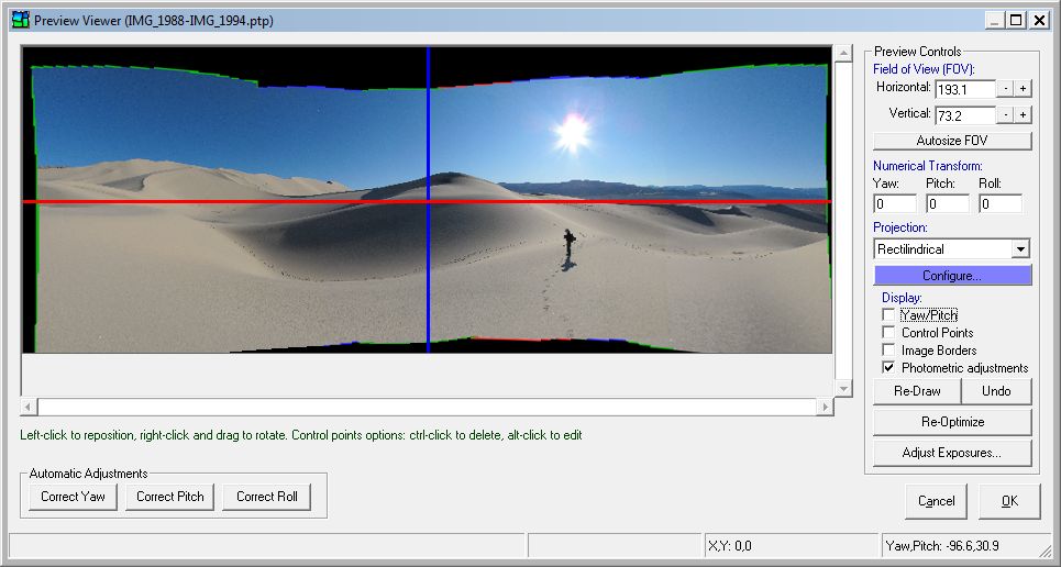
Preview image. Reference point lies at intersection of red/blue lines
The preview viewer/editor screen allows you to view a small-scale preview of your project before creating a final image. This screen also allows you to make a number of adjustments to the project and see the effects of these changes immediately. The operation of this screen is similar to the Reference Point Picker Screen, although this screen allows you to view the entire project, rather than a single image.
The preview viewer always displays the image so that the reference point of the project is at the intersection of the red and blue lines drawn on the screen. The reference point is always at the exact location where yaw and pitch both equal zero in the final image.
It is important to note that stitcher outputs a final image that has the same amount of space above and below the red "horizon line" horizon and the same amount of space to the left and right of the blue "meridian line". Because of this, some empty black space may be visible at the edges of the image, although this can be easily removed in an image editor once the final image has been created, and/or can be automatically removed by PTAssembler using the option to crop black space on the behavior tab of the preferences screen.
To reset the reference point (and move the panorama), left-click anywhere in the screen. The reference point will be moved to the location where you clicked and the image will be redrawn. For example, if you click below the red line (the "horizon line", where pitch=0), the point where you clicked will become the new reference point, and the preview image will appear to shift upwards on the screen. Clicking to the right of blue line (the "meridian line") will move the reference point to the right, and shift the image towards the left side of the screen as a result of the repositioned reference point. It is also possible to position the reference point outside of the preview image (by clicking in the black space area outside the image). This can be useful if all of the images in the project were taken with the camera pointing above or below the horizon, so that the horizon doesn't appear in the final image.
To rotate the image, move the cursor so that it is positioned over the blue line. (It is easier if you position the cursor at some distance from the intersection of the blue and red lines, rather than close to the intersection). Next, while keeping the right mouse button pressed, move the mouse to rotate the red and blue lines. Release the right mouse button once you have finished rotating the red and blue lines and the image will be redrawn so that the horizon line (i.e. where pitch=0) lies along the red line.
You can also use this screen to add horizontal and vertical line control points to the project. Left click and (while holding the mouse button depressed) move the cursor to add a vertical line control point. Holding the shift key down while left clicking and moving the mouse will add a horizontal line control point. These types of "line" control points can be used by the optimizer to "straighten" the panorama (e.g. ensuring that vertical lines in a building are rendered as vertical in the output, or that the horizon where the sea meets the sky really is horizontal). After adding these types of control points you should rerun the optimizer (either by clicking the "Re-Optimize" button or by using the optimizer/Step 4 screen).
The screen also contains the following controls:
- Horizontal and Vertical Field of View. These boxes display the current field of view of the image. To adjust the field of view for the image, enter a new number in one or both of these boxes, or click the +/- buttons next to the boxes and click the "Update Preview" button to redraw the image. Using the +/- buttons will cause PTAssembler to show the new field of view by drawing yellow guidelines on the image before the "Update Preview" button is clicked. Holding the Ctrl or Shift key while clicking the +/- buttons will cause PTAssembler to adjust the field of view in smaller or larger increments. Note that PTAssembler will adjust your choices for horizontal and/or vertical field of view if they are invalid for the currently selected projection. For example, it is a mathematical impossibility to create an image with a horizontal field of view of 180 degrees or larger when using rectilinear projection, so PTAssembler will reduce any value of 180 or larger to less than 180 in this case.
- Autosize FOV. This button calculates the optimal horizontal and vertical field of view for the project so that none of the pixels from the input images lie outside the border of the final image. (Note that the optimal FOV for the project will differ, depending on which projection is selected. Also, note that you can adjust the values selected by this button by entering different values in the horizontal and vertical field of view boxes.) Once the new FOV values are calculated, PTAssembler redraws the preview image.
- Numerical Transform. These boxes allow you to reposition the panorama by adjusting the yaw, pitch and/or roll of the project. Note that the same results can be achieved by clicking in the image and/or rotating the blue line in the image. These boxes are provided for those users who find it more convenient to enter numbers directly, rather than using the viewer screen.
- Projection. This drop down box allows you to choose an alternate projection for the image. Once you have selected the desired projection, use the "Update Preview" button to redraw the image using the new projection.
- Display: Yaw/Pitch. This checkbox enables the display of a grid that shows lines of yaw and pitch (i.e. latitude and longitude) spaced 10 degrees apart. This can be useful to help in understanding how different projections affect the appearance of the final image.
- Display: Control Points. This checkbox enables
the display of the project's control points on the preview, allowing you to
quickly see the location of all the control points in the project. The
control points are color coded to indicate the optimized control point distance
(a measure of how well the images can be aligned at each point) as follows:
- Blue: optimized distance of no more than 1 pixel
- Blue-Green mix: optimized distance of 1-3 pixels
- Green: optimized distance of 3 pixels
- Green-Yellow mix: optimized distance of 3-5 pixels
- Yellow: optimized distance of 5 pixels
- Yellow-Red mix: optimized distance of 5-7 pixels
- Red: optimized distance of at least 7 pixels
Vertical, horizontal and straight line control points are drawn as lines on the screen. Vertical control points are orange, horizontal control points are blue, and straight line control points use a variety of different colors. Control points that are part of a stacking group are displayed as square, while all other control points are displayed as circular. Holding the shift key down while clicking this checkbox will force PTAssembler to display only those control points that are part of a stacking group. Holding the alt key down while clicking this checkbox will force PTAssembler to display all control points that are not part of a stacking group.
When control points are displayed on the screen, three additional operations are possible:- Left-clicking on a control point while pressing the control button deletes the control point. The control point is immediately and permanently deleted from the project.
- Left-clicking on a control point while pressing the alt button closes the preview viewer/editor and displays the control point in the Control Points screen
- Right-clicking and dragging the mouse while pressing the control key draws a rectangular region on the preview screen. When the right mouse button is released, any control points inside the rectangular region are deleted.
- Display: Image Borders. This checkbox enables the display of colored outlines of the individual images in the project. This allows you to easily visualize the relative position of images, the amount of overlap and (when combined with the control point display) where the control points lie within the overlap regions between images. The images are identified with their image numbers in a small circle or square at the corner of each image border. If the number is inside a square, then the image uses camera position parameters. If the number is inside a circle, then the image does not use camera position parameters.
- Display: Photometric adjustments. This checkbox toggles the use of photometric adjustments (exposure, whitebalance, vignetting) when displaying the images. When checked, the preview is drawn using all photometric adjustments; when unchecked, the preview is drawn without any photometric adjustments.
- Re-Draw. This button causes PTAssembler to redraw the preview image using the settings (i.e. FOV, numerical transform, projection) currently selected on the screen.
- Undo. This button reverts the image to the most recent previous preview image. PTAssembler remembers the complete history of all previews, so this button can be clicked repeatedly.
- Re-Optimize. This button causes PTAssembler to run the optimizer and redraw the preview after the optimizer has finished. This is useful if you have added some vertical and/or vertical line control points to the project, and wish to rerun the optimizer without leaving the preview screen. Note, however, that when the optimizer is run from the preview screen, PTAssembler makes a "best guess" decision about which position parameters (yaw, pitch, roll) should be optimized for which images, based on the type and distribution of control points as well as the currently selected projection and FOV. In most cases, PTAssembler should be able to make a reasonable decision on your behalf, but for complete control you should run the optimizer manually via the Step 4 screen. Because optimizing the project usually shifts the relative position of images within the project, PTAssembler redraws each input image on the screen one at a time. Also, the "undo" button is reset, so that you can not recall previews prior to optimizing.
- Correct Exposures... This button shows the photometric adjustment screen where adjustments can be made to improve the exposure, whitebalance and vignetting in the project images.
- Automatic Adjustments. These buttons
adjust the position of the panorama as follows:
- Correct Yaw: This button adjusts the preview so that it is horizontally centered around the blue line. This is useful if the image appears shifted towards the left or right.
- Correct Pitch: This button estimates the correct pitch for the project. It performs the same function as the "Auto-Level" button on the Optimizer Screen
- Correct Roll: This button estimates the correct roll for the project. It performs the same function as the "Auto-Rotate" button on the Optimizer Screen
- OK / Cancel. If you are happy with the preview image, and any changes you have made to it using the preview viewer/editor, then click OK. This will update the current project with your changes, and calculate the optimal size (width and height) for the final image on the Step 5 screen. If you want to discard any changes made on this screen, and revert the project back to its initial state before the preview was created, click the Cancel button.
The screen responds to the following keyboard buttons:
- L Shift image left by one degree
- R Shift image right by one degree
- U Shift image up by one degree
- D Shift image down by one degree
- C Rotate image clockwise by one degree
- A Rotate image anticlockwise (counterclockwise) by one degree
- V Expand vertical field of view by one degree
- H Expand horizontal field of view by one degree
- Shift V Contract vertical field of view by one degree
- Shift H Contract horizontal field of view by one degree
The status bar at the bottom of this screen has four panels (described from left to right):
- Progress bar. Shows progress of operation while drawing image.
- Control Point Info/Size. When control points are displayed on the screen, and the cursor is positioned over a control point, this panel shows the images to which the control point belongs, and its optimized distance (i.e. how well the images are aligned at this point). When control points are not displayed, this panel shows the size of the preview image.
- X,Y Position. This panel shows the x,y position of the cursor relative to the top left corner of the preview.
- Yaw, Pitch Position. This panel shows the yaw and pitch position of the cursor relative to the center of the image (i.e. the reference point).
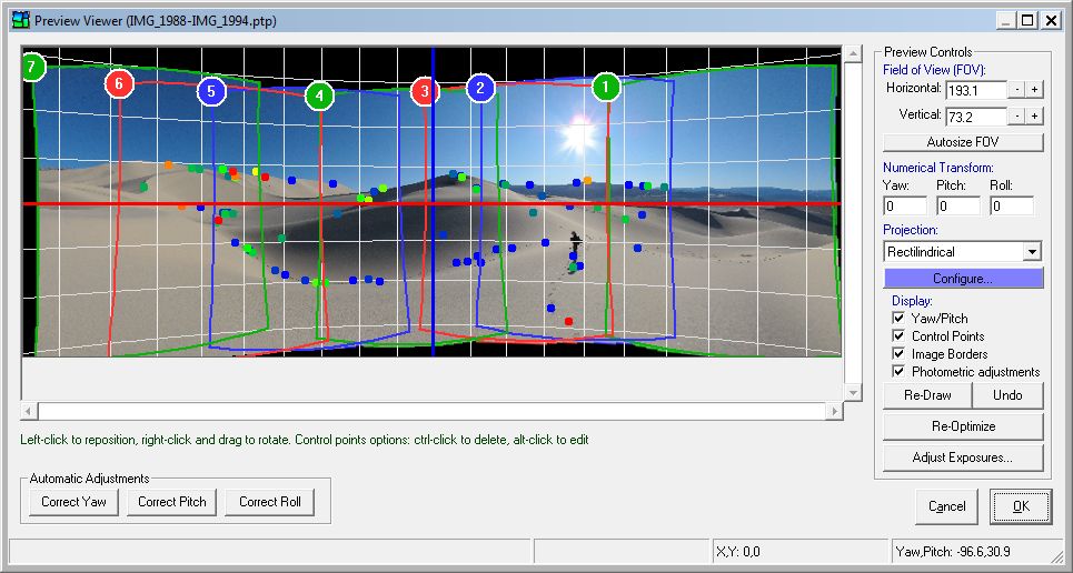
Preview image with optional display of yaw/pitch lines, control points, and image borders
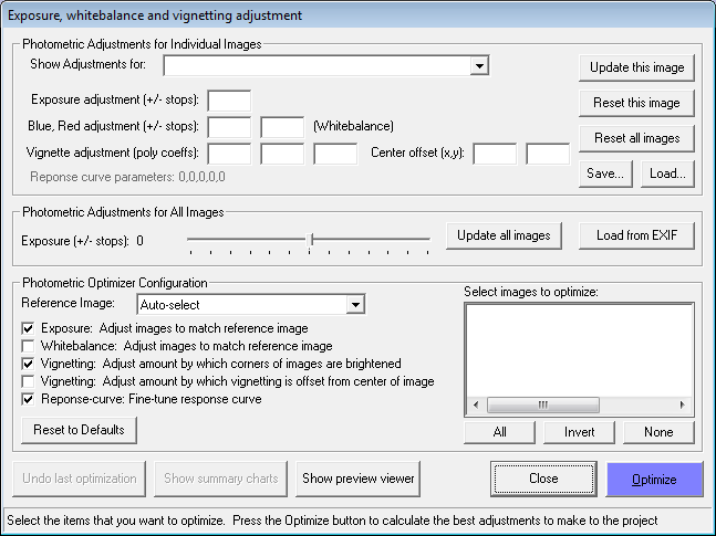
This screen allows you to make adjustments to the exposure, whitebalance and/or vignetting in the source images in a project. These are also referred to as "photometric" adjustments. (This page presents an example illustrating the impact of applying photometric adjustments to a project.) This screen can be invoked from the menu or preview viewer. The purpose of this screen is to calculate the adjusmtents necessary to minimize any exposure and whitebalance differences between images, and remove the effects of vignetting (image corner darkening). Any adjustments that are configured on this screen are applied to the images during the stitching process. Note that the original source images are never modified; rather, the adjustments are applied to the output images during the remapping/stitching process.
Photometric Adjustments for Individual Images. The top frame on this screen shows the currently configured adjustments for each image in the project. By default, all adjustments are set to zero. Adjustments for individual images can be manually entered if desired, but this is not usually necessary because PTAssembler can typically deduce the best adjustments to make for each image using the photometric optimizer (described below).
The values for exposure and whitebalance are measured in stops (one stop implies a doubling of exposure or intensity). Whitebalance adjustments are made by adjusting the intensities of the blue and red channels relative to the green channel. PTAssembler uses a formula that relates the amount of darkening to the distance from the center of the image. The first three vignetting adjustment values (labelled "poly coeffs") are the parameters for this formula. In general larger values imply more adjustment is necessary. The last two values (labelled "Center offset") allow for the center of vignetting to be offset from the center of the image (these values are measured in pixels).
PTAssembler also shows the values for the "response curve" in this frame. The response curve describes the relationship between the light intensities measured by a camera's sensor and the light intensities that are recorded in the image files produced by that camera. Almost all cameras use a response curve to adjust the light intensities measured by their sensor before writing an image file, and this response curve must be taken into account by PTAssembler before making photometric adjustments. Because the response curve is unkown, and varies from one camera to another (and often from one camera setting to another), PTAssembler assumes a default response curve which should work well under most circumstances, but can be "fine-tuned" by the photometric optimizer based on the images themselves.
The update and reset buttons in this frame allow you to update and/or reset the photometric adjustment values for one or all images in the project.
The Save and Load buttons allow you to save and load photometric parameters, which is documented here.
Photometric Adjustments for All Images. This frame contains two features:
- A slider that allows you to make adjustments to exposure for all images the project. The slider configures the amount (measured in stops), and the "update all images" button applies this adjustment to all images in the project. This can be useful if you want to make the final panorama brighter or darker.
- The "Load from EXIF" button makes PTAssembler attempt to read the EXIF exposure information (derived from shutter speed, aperture and ISO) from all images in the project. If this data is found, PTAssembler will assign the appropriate exposure adjustment values for each image to ensure a constant exposure across all images in the project.
Photometric Optimizer Configuration. This frame allows you to configure the photometric optimizer. The purpose of the optimizer is to analyze the images in your project, look for differences in exposure, whitebalance and/or vignetting, and determine the most appropriate adjustments to make to each image. In order for the optimizer to calculate meaningful adjusments, the images must already be aligned (i.e. the yaw, pitch, roll must have already been optimized) so that the photometric optimizer knows how to analyze the images. If the images are not already aligned, the photometric optimizer will not produce good results.
The photometric optimizer requires a "reference image" when determining the appropriate exposure and whitebalance adjustments for the other images in the project. The optimizer tries to match the exposure and whitebalance in the other images to the exposure and whitebalance for the reference image. By default, PTAssembler "auto-selects" a reference image, but you can manually specify one instead.
By default, the photometric optimizer will find adjustments for exposure and vignetting. It will also attempt to "fine-tune" the default response curve. The checkboxes in this frame allow you to configure what adjustments the photometric optimizer should estimate. It is a good idea to only check those adjustments that are necessary. For example, if the whitebalance is identical for all images in a project, then leave the whitebalance checkbox unchecked.
You can choose the images for which the photometric optimizer will attempt to find adjustments, selecting the desired images in the image list in this frame. By default, PTAssembler will include all images when running the photometric optimizer, but this can be changed as needed.
Photometric Control Buttons. This screen contains the following control buttons.
- Undo last optimization. Reverts the photometric adjustments back to their values prior to the last run of the photometric optimizer.
- Show summary charts. Shows a page with a number of charts (example here) summarizing the photometric adjustments estimated during the most recent run of the photometric optimizer. This button is disabled until the photometric optimizer has been run. These charts are presented in a web-page that is displayed by your computer's default web-browser. The charts utilize the google charts API, and require an internet connection in order to display correctly.
- Show preview viewer. Shows the preview viewer screen.
- Close. Closes this screen.
- Optimize. Runs the photometric optimizer using the options configured on this screen. The optimizer attempts to find the best adjustments to make to the selected images. After the optimizer has completed, the project is updated with the adjustments calculated by the optimizer.
The status bar at the bottom of the screen gives a summary of the amount by which photometric errors (i.e. differences in exposure and whitebalance in overlapping images) are reduced when the photometric optimizer is run. It also give a summary of the range of current adjustments for the images in the project.
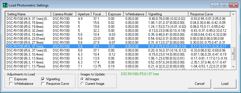
This screen can be used to load photometric settings for one or all images in the current project. Photometric settings can be saved from one project, and then reapplied to another project using this screen. Each row on this screen represents one photometric settings record, and is identified by a user-specified name, Camera Model, Aperture and Focal Length. When this screen is shown, PTAssembler attempts to highlight the record that is most appropriate for use with the current image, (based on similarity to camera model, aperture and focal length). In the bottom right of the screen, the current image's camera model, aperture and focal length are shown (if available). If a good match is found with an existing photometric preset this label is colored green. If a weak match is made, the label is red. If no match (or a poor match) is found, then the color is black.
The "Adjustments to Load" frame allows you to specify which settings to apply to the current image(s). The "Images to Update" frame allows you to choose whether to apply the settings to just the current image, or all images in the project.
To delete a row from this table, right-click the entry to delete, and use the delete menu option.
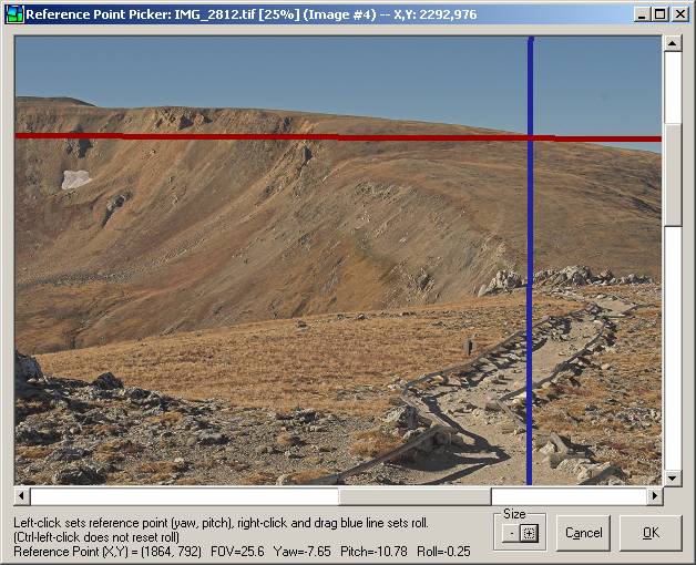
The 'reference point' for any stitched panorama is the point in the scene that was straight ahead at eye level when you took the images in your project. This point is used by PTAssembler to estimate the Yaw, Pitch and Roll value for the image that contains it (i.e. the 'reference image'). (Note: See the preferences screen for an option that allows the reference point picker to assign the roll value for all images simultaneously).
The reference point is the point that you would have seen when you looked straight ahead when you were taking the images in this project. If the camera was level (i.e. not pointing up or down) when the images were taken, the 'reference point' should be (as close as possible to) the desired center (before cropping) of the final panorama. If the camera was pointing upwards (e.g. from street level towards the top of a building) then the 'reference point' will be in the bottom half of the image, near the ground floor of the building. Conversely, if the camera was pointed down (e.g. from the top of a mountain down into a valley) to take the images, then the 'reference point' will be near the top of the image.
An important point to grasp is that the reference point is the center point (before cropping) of the final panorama. There will be an equal area above and below this point in the final image, and an equal area left and right of this point (unwanted "empty" space can be cropped away after the final image is produced). The reference point can be changed at any time, and can also be modified using the preview screen. The key point is that the reference point should be placed at eye-level, when looking straight ahead.
What happens if the reference point is not positioned at eye-level looking straight ahead? PTAssembler will still produce a panorama, but you may notice that the horizon becomes "bowed" into a frown or a smile shape. Similarly, vertical lines that should be vertical may appear to lean, or converge towards each other. (Advanced users: If an artistic judgment is made that this is the intended result---for example, a curved horizon or leaning buildings--then the reference point can be placed anywhere desired.) You may need to experiment to find the exact location of the reference point, but you can always come back to this screen (or the preview screen) and adjust your choice later.
In order to set the reference point, click the mouse on the point where you want to set the reference point. This will set the yaw (i.e. left/right position) and pitch (i.e. up/down position). To set the roll, move the cursor so that it is positioned over the blue line. (It is easier if you position the cursor at some distance from the intersection of the blue and red lines, rather than close to the intersection). Next, press and hold the right mouse button down and move the mouse to rotate the lines. You should rotate the lines so that the red line is parallel to the horizon and the blue line is parallel to any vertical features in the image. As you rotate the lines, you will notice that the roll value displayed at the bottom of the screen will change.
The Size buttons on this screen allow you to change the size of the image, making it easier to see the desired location for the reference point when working with large images.
The preferences screen contains multiple tabs, which are described in detail below:
- Files/Dirs
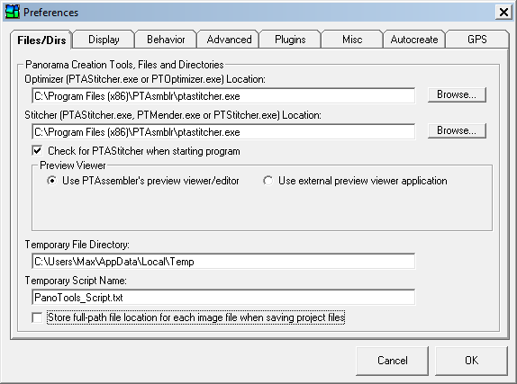
- Optimizer location. Specifies the location of the optimizer. The default optimizer is PTAStitcher, but PTAssembler is still compatible with the older PTOptimizer program that is part of Panorama Tools.
- Stitcher location. Specifies the location of the stitcher. The default stitcher is PTAStitcher, but PTAssembler is still compatible with the older PTStitcher and PTMender programs that are part of Panorama Tools.
- Check for PTAStitcher... If checked, and PTOptimizer, PTStitcher and/or PTMender are currently configured as the stitching and/or optimizing programs, PTAssembler prompts the user to set PTAStitcher as the optimizing/stitching program.
- Preview Viewer. Select whether to use PTAssembler's
internal preview viewer/editor or an external application.
The internal preview viewer/editor allows you to edit/adjust the preview graphically,
unlike an external preview application, which does not provide this capability.
If you select the option to use an external preview viewer application several
other fields become visible:
- Viewer Application. Specify the location for the preview viewer You may use Internet Explorer web browser (search for iexplore.exe to locate this program on your computer) or a standalone image viewer such as Irfanview works even better.
- Use system default viewer application. If checked, PTAssembler will use Windows file associations to determine and use your system's currently configured default application for viewing images. If checked, the choice specified for "Viewer Application" (above) is ignored.
- Temporary Directory. Location where PTAssembler creates/stores temporary files. (Note: Auxiliary programs and plugins specify their own temporary directories).
- Temporary Script Name. Name used by PTAssembler when creating script files.
- Store full-path file location... If checked (default value), PTAssembler will store full path information about all images in a project (e.g. "c:\images\Jan2003\image01.jpg"). This enables you to save the project file in any directory, regardless of where your images are located. If unchecked, PTAssembler will store only the file name (e.g. "image01.jpg"). The project file must be saved in the same directory as the images. However, because the full-path information is not recorded, you can move the image and project file to another directory without having to edit the project file to adjust the path name for each image.
- Display
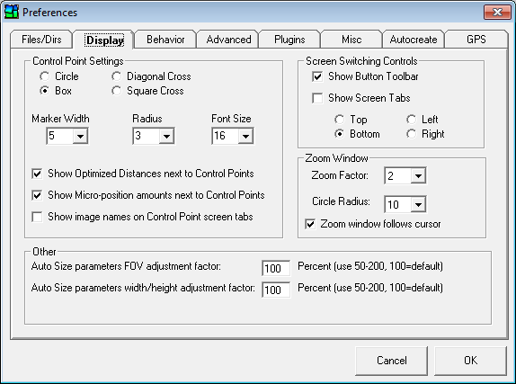
- Control Point Settings. These options determine the appearance of the control points (and associated text) in the image viewers on the Step 3 screen. The "Show image names on Control Point screen tabs" checkbox allows you to display the names of the images on the tabs used to display images on the Step 3 screen.
- Screen Switching Controls. Determines the graphical controls used by PTAssembler to switch between screens.
- Zoom window. Sets options for the zoom window that displays an enlarged version of the image on the Step 3 screen.
- Auto size parameters FOV adjustment factor. This adjusts the estimate for FOV produced by the 'Auto Size Parameters' button on the Step 5 Screen. The default value of 100 percent should produce reasonable estimates, but you can enlarge or reduce the values produced by adjusting this number.
- Auto size parameters width/height adjustment factor. This adjusts the estimates produced for width and height by the 'Auto Size Parameters' button on the Step 5 Screen. It also adjusts the values that are populated for full-size width and height after closing the internal preview viewer/editor. The default value of 100 percent should produce reasonable estimates, but you can enlarge or reduce the values produced by adjusting this number.
- Behavior
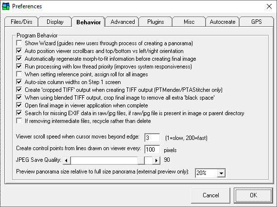
- Program Behavior. Several options that change the behavior of the program.
- Show wizard... Displays PTAssembler's wizard which guides a new user through the basic steps needed to create a panorama.
- Auto position viewer scrollbars... Depending on where control points are clustered (i.e. along left/right edges or top/bottom), PTAssembler will try to determine the orientation of your images (i.e. side-by-side, or stacked top-to-bottom), and display the images appropriately on the Step 3 screen.
- Automatically regenerate morph-to-fit information... When using Panorama Tools' morph-to-fit feature (see Step 2), it is crucial that the dimensions of the final panorama (see Step 5) are not changed after the optimizer (see Step 4) has been run. To ensure that the morph-to-fit data is always up-to-date, this feature will run the optimizer briefly immediately before creating a final panorama.
- Run processing with low thread priority... If checked, PTAssembler will launch the stitcher and any other external programs as a low-priority process (instead of normal-priority). This will make the system more responsive to other programs because low-priority processes are preempted by any other processes or programs running in a higher priority class.
- When setting reference point, assign roll for all images. If unchecked, the reference point picker will assign the yaw, pitch and roll for only the reference image. If checked, the yaw and pitch will be assigned for the reference image only, but the roll will be assigned for all images in the project.
- Auto-size column widths on Step 1 screen. If unchecked, PTAssembler will automatically resize the columns in the table on Step 1. If unchecked, the user can modify the widths of these columns, and PTAssembler will not change the widths.
- Create 'cropped TIFF' output when creating TIFF output... If checked, PTAssembler will instruct the stitcher to output "cropped TIFF" files when writing "Multiple image TIFF" output or "Single layer TIFF" output (doesn't work with PTStitcher). The dimensions of these Cropped TIFF files are the size of the smallest rectangle needed to encompass the output image, without including any extra "empty space" around the image that is characteristic of full size image output. Information about the offset of this "cropped" image rectangle from the top corner of the "full size" image from which it was cropped is included in the TIFF file header and can be used by programs (such as Smartblend, Enblend and multiblend) that (a) look for this information and (b) do something with this information. The file sizes of Cropped TIFFs are considerably smaller than full size TIFFs, and generate much faster than full size TIFFs...particularly for projects with large numbers of images.
- When using blended TIFF output, crop final image to remove all extra 'black space' If checked, PTAssembler will trim all remaining "black space" from around the final blended output produced by the blending program (Smartblend, Enblend or Multiblend). PTAssembler attempts to crop all black or empty space from the blended image, but leave as much image as possible.
- Open final image in viewer application when complete If checked, PTAssembler will attempt to open the final image in the viewing application configured on the Files/Dirs tab.
- Search for missing EXIF data in raw/jpg files...When checked, if PTAssembler cannot locate EXIF data in a source image, PTAssembler will attempt to locate a correspondingly named raw file (with .crw, .cr2 or .dng file extension) ir JPG file (with .jpg or .jpeg extension) in the same directory or parent directory as the source image and extract EXIF data from the raw image, if possible. This can be useful if the image being used in the project doesn't contain all of the EXIF data contained in a corresponding raw/JPG version of that image.
- If removing intermediate files, recycle rather than delete If intermediate files are removed after processing (configured on the processing options screen), determines if files are deleted permanently or moved to the recycle bin.
- Viewer scroll speed... Determines how quickly the viewers scroll on the step 3 screen when the cursor goes beyond the boundaries of the image viewer.
- Create control points from lines... Determines the frequency with which control points are placed along lines drawn on the viewer windows (see step 3) when converting lines to control points.
- JPEG save quality. Determines the quality of any files saved in JPEG file format.
- Preview panorama size... Determines the size of the preview panorama that is suggested when the Auto-size parameters button (see step 5) is pushed. Note that this option does not pertain to the previews created by PTAssembler's internal preview viewer/editor, which calculates its own preview size. This option only sets the size for previews that are shown in external preview applications.
- Advanced
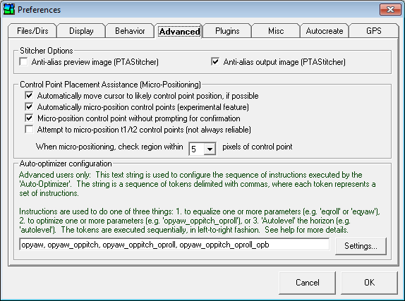
- Anti-alias preview image. If checked, PTAStitcher will perform "anti-aliasing" if it detects that the image is being significantly downsampled during remapping. Downsampling occurs when the output image is considerably smaller than the input image(s), which typically happens during preview generation. Anti-aliasing improves the appearance of straight lines which can appear "jagged" if anti-aliasing is not performed. However, anti-aliasing slows the speed with which the preview may be generated, so if speed is a concern, you may wish to uncheck this box.
- Anti-alias output image. If checked, PTAStitcher performs "anti-aliasing" on the output image. See the description for "Anti-alias preview image" above for more details.
- Automatically move cursor to likely control point position, if available. If checked, PTAssembler will automatically try and locate the matching control point for any selected control point in the Step 3 screen. This feature requires at least one control point to already be selected for each pair of images before it is activated. PTAssembler will move the cursor to the location in the opposite viewer window where it thinks the matching control point should be located. Note that this feature is affected by the accuracy of your existing control point locations and the distortion in your images. Currently, this feature only works for rectilinear images.
- Automatically micro-position control points... An experimental feature to try and 'micro-reposition' control points for more precise positioning. After you create a control point by clicking in both viewer screens (See Step 3), PTAssembler will examine a small area around the control point to try and correct any minor (i.e. a few pixels) misalignment of the control point. Note: This feature is turned off by default because it is experimental and may not work correctly for all images under all circumstances.
- Micro-position control point without prompting for confirmation. If checked, PTAssembler will reposition the control point without prompting for confirmation.
- Attempt to micro-position t1/t2 control points... If checked, PTAssembler will attempt to micro-position vertical line (t1) or horizontal line (t2) control points. Because micro-positioning works best on regions with identical features, and because t1 and t2 control points are generally not located on identical features, this option is disabled by default.
- When micro-positioning, check region within... Determines the size of the area around each control point in which PTAssembler will search for a better alignment. Larger values may take a long time to search. With care, you should be able to manually place a control point within 2 or 3 pixels of its correct position, so a value of larger than 3 to 5 pixels is not usually needed.
- Auto-optimizer configuration. Allows you to enter a text string that
configures the sequence of optimization steps performed by PTAssembler when the 'Auto Optimize' button is pressed
on the Step 4 screen.
The text string is a sequence of tokens delimited with commas, where each token represents a set of instructions
(i.e. one run of the optimizer = an "instruction set"). Each "instruction set" consists of one
ore more "instructions" separated by an underscore.
Instructions are used to do one of six things:
- to equalize one or more parameters (using 'eqroll', 'eqyaw', 'eqpitch')
- to optimize one or more parameters (using 'opyaw', 'oppitch', 'oproll', 'opa', 'opb', 'opc', 'opd', 'ope', 'opg', 'opt', 'opv')
- to link parameters (using 'linka', 'linkb', 'linkc', 'linkd', 'linke', 'linkg', 'linkt', 'linkv')
- to unlink parameters (using 'unlinka', 'unlinkb', 'unlinkc', 'unlinkd', 'unlinke', 'unlinkg', 'unlinkt', 'unlinkv')
- to 'Autolevel' the horizon (using 'autolevel')
- to 'Auto-rotate' the project (using 'autoroll')
Multiple instructions can be combined in one instruction set using an underscore character (e.g. 'eqyaw_eqroll_opyaw_oppitch_oproll'). There is no limit to the number of instruction sets that can be specified. Instruction sets are executed one at a time, in left-to-right fashion. Within each instruction set, the operations are executed in the following order:
- Equalize instructions (e.g. 'eqyaw', 'eqroll')
- Link/Unlink instructions (e.g. 'linkb', 'unlinkv')
- Optimizer instructions (e.g. 'opyaw', 'oppitch')
- Auto-level instructions (i.e. 'autolevel')
- Auto-rotate instructions (i.e. 'autoroll')
Note that if an "unlink" instruction is encountered (e.g. "unlinkv"), then the project value for that parameter is propagated to all images in the project. For example, "unlinkv" would take the project value for FOV and assign it each image in the project. The opposite is not true. For example, a "link" instruction does not cause the parameter value from any single image to be assigned to the corresponding project parameter.
The following is an example of a simple auto-optimizer string:
opyaw, eqyaw_opyaw_oppitch_oproll_opb, autolevel
This example contains three instruction sets executed in left-to-right order:
- opyaw. Optimize the yaw parameter
- eqyaw_oppitch_oproll_opb. Equalize yaw, and then optimize yaw, pitch, roll and b
- autolevel. Autolevel the horizon
The Auto-optimizer generally works best when a reference image has been selected. In the absence of a reference image, and if yaw, pitch and roll is optimized, the lack of any image to act as an "anchor" can produce what appears to be random repositioning of the entire project unless Horizontal Line and Vertical Line (t1 and t2) control points have been selected. The existence of these "line" control points can give the optimizer information about the correct absolute positioning of the project. (See below for more information about using auto-optimizer with horizontal or vertical line control points).
The way in which requested parameters are optimized depends on if a reference image is selected or not. For example, if a reference image is selected, the auto-optimizer will optimize all position parameters (i.e. yaw, pitch, roll) for all images in the project, except for the reference image. If no reference image is selected, then it will optimize position parameter values for all images which can lead to the repositioning problem described above.
If unlinked (i.e. parameters are allowed to vary for each image in the project), lens distortion and shift parameters (a,b,c,d,e,g,t) are optimized for all images in the project regardless of whether a reference image is selected or not. FOV is handled slightly differently...if a reference image is selected and if FOV is "unlinked" (i.e. allowed to vary for each image in the project), then FOV is optimized for all images except the reference image. If no reference image is selected, and FOV is "unlinked", then FOV is optimized for all images in the project. If any of the distortion/shift/fov parameters are linked (i.e. forced to be the same for all images in the project), the selection of a reference image makes no difference...the parameters are optimized.
Note that the auto-optimizer works differently when invoked with projects that contain Horizontal Line or Vertical Line (t1 or t2) control points when compared to projects that don't contain these types of control points. For example, Vertical Line control points give the optimizer valuable clues for the correct value for the pitch and roll parameters. Because of this, if PTAssembler detects that the project contains 2 or more Vertical Line control points, it will generally choose to optimize the pitch and roll parameters for all images including the reference image (if selected). PTAssembler's auto-optimizer will also ignore any instructions to equalize the pitch or roll parameters, as this would overwrite the values calculated by the optimizer. Similarly, when PTAssembler detects 2 or more Horizontal Line control points in the project, it typically will optimize the yaw and roll parameters for all images in the project, and ignore any instructions to equalize the yaw or roll parameters. (The exact logic depends on a number of other factors as well, including the projection type). Note also that the auto-optimizer always specifies rectilinear (for panoramas with FOV < 180 degrees) or equirectangular projection (for panoramas with FOV >= 180 degrees) to the optimizer (regardless of the current setting on Step 2 screen).
Because of the way in which the auto-optimizer behaves in the presence of Vertical line and Horizontal line control points, it is not necessary to select a reference image or point if the project contains 2 or more Vertical Line control points and 2 or more Horizontal Line control points.
- Settings... Displays the auto-optimizer configuration screen where you can select from several different auto-optimizer instruction set presets.
- Plugins
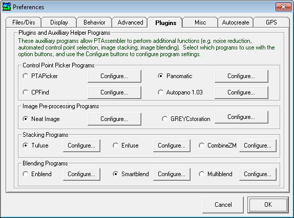
- Control Point Picker Programs. PTAssembler can use one of four different
control point picker programs: PTAPicker, Panomatic, CPFind, Autopano.
PTAPicker is created by Tawbaware and is distributed with PTAssembler. The three other programs are
written by different authors. Only one program can used at a time from within PTAssembler. All programs
are designed to automatically find control points between overlapping images. It is not necessary to
have any of these programs installed in order to run PTAssembler, but they allow for the
automatic creation of control points and one is necessary in order to use PTAssembler's Autocreate feature.
Select the program you wish to
use by selecting the appropriate option button. Options (described below) for
these programs can be configured by clicking the "Configure..." button.
- PTAPicker (distributed with PTAssembler) is written by Tawbaware.
- PTAPicker.exe Location. Specify the location where PTAPicker is installed. This location is automatically specified as part of the standard PTAssembler installation. You should only change this if you want to use a different version of PTAPicker than the one distributed with PTAssembler.
- Command line arguments. Specifies any optional command line arguments that are sent to PTAPicker. These arguments are optional and can be left blank if desired. Please consult the PTAPicker documentation for the meaning and behavior of these options.
- Reset Resets the optional command line arguments used by PTAssembler when launching PTAPicker.
- Panomatic (download link at bottom of page)
is written by Anael Orlinski. PTAssembler works with version 0.94 (and possibly later versions) of Panomatic.
- Panomatic.exe Location. Specify the location where you have installed Panomatic. If not specified, then PTAssembler will not be able to use Panomatic.
- Command line arguments. Specifies any optional command line arguments that are sent to Panomatic. These arguments are optional and can be left blank if desired. Please consult the Panomatic documentation for the meaning and behavior of these options.
- Reset Resets the optional command line arguments used by PTAssembler when launching Panomatic.
- CPFind (download link at bottom of page)
is open-source software, distributed with Hugin. PTAssembler works with version 2012.0.0 (and possibly later versions) of CPFind.
- CPFind.exe Location. Specify the location where you have installed CPFind. If not specified, then PTAssembler will not be able to use CPFind.
- Command line arguments. Specifies any optional command line arguments that are sent to CPFind. These arguments are optional and can be left blank if desired. Please consult the CPFind documentation for the meaning and behavior of these options.
- Reset Resets the optional command line arguments used by PTAssembler when launching CPFind.
- Autopano (download link at bottom of page)
is written by Alexandre Jenny. PTAssembler works with version 1.03 (but not older versions) of Autopano.
Autopano does not appear to work with Windows 7/8, and is no longer recommended as a control point picker program.
- Autopano.exe Location. Specify the location where you have installed Autopano. If not specified, then PTAssembler will not be able to use Autopano.
- Command line arguments. Specifies any optional command line arguments that are sent to Autopano. These arguments are optional and can be left blank if desired. Please consult the Autopano documentation for the meaning and behavior of these options.
- Reset Resets the optional command line arguments used by PTAssembler when launching Autopano.
- PTAPicker (distributed with PTAssembler) is written by Tawbaware.
- Image Pre-Processing Programs. PTAssembler "pre-process" the images
before starting the stitching process. The pre-processing program will not overwrite your original images, but rather
creates temporary output images that are subsequently used as inputs to the stitcher. Once
the stitching process finishes, these temporary images are deleted. You must configure the pre-processing
program using the "configure..." button before it can be used. In order to activate pre-processing,
use the "Enable pre processing" checkbox on the Step 5 screen.
Currently, the following pre-processing programs are supported by PTAssembler:- Neat Image: Neat Image (download link at bottom of page) is an image noise reduction program sold by Absoft. In order to use Neat Image to pre-process images, you need to tell PTAssembler where it is installed, and which noise profile and filter preset to use. Use the "configure..." button to specify this information. PTAssembler has been tested with Neat Image Home Edition, version 5.6. PTAssembler may work with earlier and later versions of Neat Image Home and Pro editions, but will not work with the Neat Image Demo Edition because it cannot be controlled via the command line.
- GREYCstoration: GREYCstoration (download link at bottom of page) is an open source image noise reduction program written by David Tschumperl�. In order to use GREYCstoration to pre-process images, you need to tell PTAssembler where it is installed. Use the "configure..." button to specify this information. PTAssembler has been tested with GREYCstoration, version 2.5. The configuration screen also has an interactive previewer that allows to adjust GREYCstoration parameters and determine how much or little noise is reduced. See this section for more information about this screen.
- Stacking Programs. PTAssembler is distributed with its own stacking plugin program called "TuFuse".
In addition to TuFuse, PTAssembler can also be configured to work with Enfuse or CombineZM as a stacking plugin.
Select the stacking program you wish to use by selecting the appropriate option button next to TuFuse, Enfuse or CombineZM.
In order to either program Enfuse or CombineZ, you must download and install the program(s) (neither is distributed with PTAssembler) and
configure the program location(s) on this screen. To create an image with a stacking program,
select the appropriate stacking option on the processing options screen.
- TuFuse (included with PTAssembler).
Tufuse is designed to blend multiple images of the same scene taken with different exposures and/or different
focus settings into a single "extended focus/extended dynamic range" image. TuFuse is able to perform
both exposure blending and focus blending as a single operation.
- Configuration presets. Choose one of the configuration presets to populate the command line arguments for TuFuse.
- Enfuse Command line arguments. Manually specify or modify command line arguments to be sent to Tufuse. Please consult the Tufuse documentation for the meaning of these options.
- Enfuse (download link at bottom of page).
Enfuse is designed to blend multiple images of the same scene (taken with different exposures) into a single
"extended dynamic range" image. PTAssembler works with version 3.1 (and possible later versions) of Enfuse
- Location. Specify the location where you have installed Enfuse. If not specified, then PTAssembler will not be able to use Enfuse.
- Enfuse Command line arguments. Specifies additional command line arguments to be sent to Enfuse. Please consult the Enfuse documentation for the meaning of these options.
- Reset Arguments. Resets the command line arguments used by PTAssembler when launching Enfuse.
- CombineZM (download link at bottom of page).
CombineZM is designed to blend multiple images of the same scene (taken with different
focus settings) into a single "extended focus" or "extended depth of field" image.
- Location. Specify the location where you have installed CombineZM. If not specified, then PTAssembler will not be able to use CombineZM.
- CombineZM Command line arguments. Specifies additional command line arguments to be sent to CombineZM. Please consult the CombineZM documentation for the meaning of these options.
- Reset Arguments. Resets the command line arguments used by PTAssembler when launching CombineZM.
- TuFuse (included with PTAssembler).
Tufuse is designed to blend multiple images of the same scene taken with different exposures and/or different
focus settings into a single "extended focus/extended dynamic range" image. TuFuse is able to perform
both exposure blending and focus blending as a single operation.
- Blending Programs. PTAssembler can use Enblend, Smartblend or Multiblend
as a blending plugin. Only one program can used at a time, however. Select the program you wish to
use by selecting the appropriate option button next to Enblend, Smartblend or Multiblend.
In order to either program, you must download and install the program(s) (neither is distributed with PTAssembler) and
configure the program location(s) on this screen. To create an image with a blending program,
select the "Blended, single layer TIFF" output file format choice on the Step 5 screen.
- Enblend (download link at bottom of page)
is a program written by Andrew Mihal, and is designed to blend the multi-layer
output from the stitching engine into one final image. It uses a superior blending technique to the stitcher's rudimentary
blending algorithm. PTAssembler works with version 3.2 (and possibly later versions) of Enblend.
- Location. Specify the location where you have installed Enblend. If not specified, then PTAssembler will not be able to use Enblend.
- Enblend Command line arguments. Specifies additional command line arguments to be sent to Enblend. Please consult the Enblend documentation for the meaning of these options.
- Reset Arguments. Resets the command line arguments used by PTAssembler when launching Enblend.
- Smartblend (download link at bottom of page) is a program written by Michael Norel, and is designed to blend the multi-layer
output from the stitcher into one final image. It is identical in purpose to Enblend, but uses a different blending
algorithm. PTAssembler works with version 1.25 (and possibly later versions) of Smartblend.
- Location. Specify the location where you have installed Smartblend. If not specified, then PTAssembler will not be able to use Smartblend.
- Smartblend Command line arguments. Specifies additional command line arguments to be sent to Smartblend. Please consult the Smartblend documentation for the meaning of these options.
- Reset Arguments. Resets the command line arguments used by PTAssembler when launching Smartblend.
- Multiblend (download link at bottom of page)
is a program written by David Horman, and is designed to blend the multi-layer
output from the stitcher into one final image. It is identical in purpose to Enblend, but uses a
different and faster blending algorithm. PTAssembler works with version 0.6 (and possibly later versions) of Multiblend.
- Location. Specify the location where you have installed Multiblend. If not specified, then PTAssembler will not be able to use Multiblend.
- Multiblend Command line arguments. Specifies additional command line arguments to be sent to Multiblend. Please consult the Multiblend documentation for the meaning of these options.
- Reset Arguments. Resets the command line arguments used by PTAssembler when launching Multiblend.
- Enblend (download link at bottom of page)
is a program written by Andrew Mihal, and is designed to blend the multi-layer
output from the stitching engine into one final image. It uses a superior blending technique to the stitcher's rudimentary
blending algorithm. PTAssembler works with version 3.2 (and possibly later versions) of Enblend.
- Control Point Picker Programs. PTAssembler can use one of four different
control point picker programs: PTAPicker, Panomatic, CPFind, Autopano.
PTAPicker is created by Tawbaware and is distributed with PTAssembler. The three other programs are
written by different authors. Only one program can used at a time from within PTAssembler. All programs
are designed to automatically find control points between overlapping images. It is not necessary to
have any of these programs installed in order to run PTAssembler, but they allow for the
automatic creation of control points and one is necessary in order to use PTAssembler's Autocreate feature.
Select the program you wish to
use by selecting the appropriate option button. Options (described below) for
these programs can be configured by clicking the "Configure..." button.
- Misc
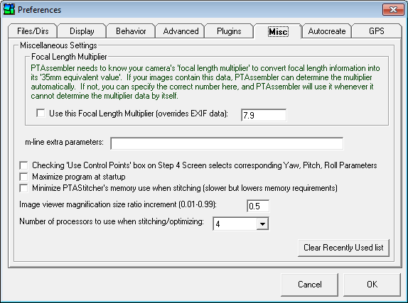
- Focal Length Multiplier. If you check this box, and specify a
focal length multiplier, then PTAssembler will use this value for the focal length multiplier
under the following circumstances:
- If the images contain some EXIF data, but not enough to calculate the multiplier, then this value will be placed into the Multiplier box on the step 2 screen when the "Calculate using image EXIF data" button is pressed.
- Even if the images contain enough EXIF data to allow this value to be calculated, this value will still be placed into the Multiplier box on the step 2 screen when the "Calculate using image EXIF data" button is pressed.
- During autocreate, this value will be placed into the Multiplier box on the step 2 screen if the images do not contain enough EXIF data to allow PTAssembler to compute it.
- m-line extra parameters. Specify any extra parameters that should be passed to the stitcher on the m-line. These parameters will be appended to the m-line that PTAssembler creates. (This can be useful when using alternate or experimental versions of Panorama Tools that require additional parameters to be passed via the m-line.)
- Checking 'Use Control Points'... If selected, the checkboxes next to the yaw, pitch and roll parameters are selected/deselected when changes are made to the entries in the 'Use Control Points From' box on the Step 4 screen.
- Maximize program at startup. PTAssembler starts with main window maximized.
- Minimize PTAStitcher's memory use when stitching. If checked, PTAStitcher uses a smaller amount of memory during stitching, but operates more slowly. Unless the images being remapped are very large, or the machine is old and/or has very little memory, there isn't normally any need to check this box. It is recommended only if errors are encountered while stitching.
- Image viewer magnification size ratio increment. Determines the amount by which the images in the image viewer windows on the Step 3 screen are magnified when the magnifier keyboard shortcuts/mouse controls ([,], alt-click, ctrl-click) are used.
- Number of processors to use when stitching/optimizing. On multi-core or multi-processor machines, PTAssembler can divide the work into multiple pieces and execute these pieces simultaneously to process projects more quickly. The exact mechanism by which this happens depends on which stitching and optimizing engines are used. When PTAssembler is configured to use PTAStitcher as the stitching engine, it is possible to divide up the work into multiple pieces regardless of output file format. However, if Panorama Tools is used, then PTAssembler can only divide the work if the output format if "Multiple image TIFF" or "Blended, single layer TIFF". Similarly, when PTAStitcher is used to optimize the project, the work can be divided across processors/cores, but not when PTOptimizer is used. Selecting "Auto" will cause PTAssembler to query the operating system, and request a count of the number of cores available. PTAssembler divides the work into the number of pieces as reported by the operating system and executes these simultaneously. Alternatively, you can specify the number simultaneous processes manually here.
- Clear Recently Used List. This removes all recently used projects from the end of the File menu.
- Focal Length Multiplier. If you check this box, and specify a
focal length multiplier, then PTAssembler will use this value for the focal length multiplier
under the following circumstances:
- Autocreate
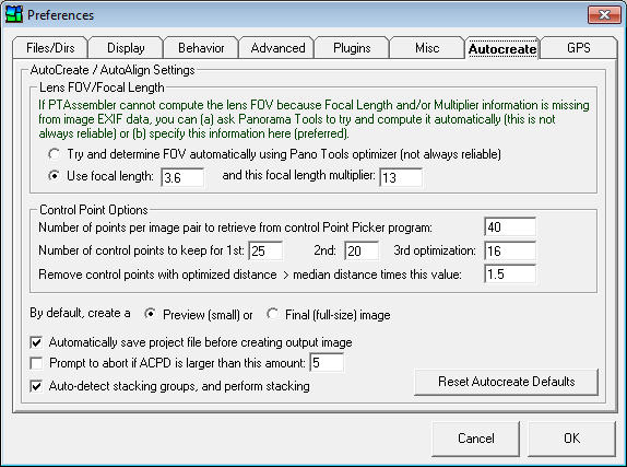
- Lens FOV/Focal Length. These options determine what PTAssembler does if it can't determine the FOV for your images during Autocreate. Using the "Try and determine FOV automatically" option will cause PTAssembler to try and determine the FOV by optimizing this parameter. This works well in some cases, but not in all. It can produce unpredictable results. As such, it is not generally recommended for all circumstances. A more reliable choice is the "Use focal length...and this focal length multiplier" option. If you know these values for your images, it is strongly recommended that you use this option for best results. Note that if you have already specified a focal length multiplier on the "Misc" tab, then the option to specify a focal length multiplier will be disabled here.
- Number of control points per image pair to retrieve from Control Point Picker program. Determines how many control points PTAssembler asks the Control Point Picker program to create.
- Number of control points to keep for 1st, 2nd, 3rd optimization. The Autocreate feature works by weeding out bad control points in an iterative process. It starts with a relatively high number of control points, runs the optimizer and then removes those that are obviously misplaced. It repeats this process three times so that at the end of the process, only a few "good" control points are retained.
- Remove control points with optimized dist > this values times median dist Establishes the threshold level for the maximum acceptable control point distance prior to the second run of the optimizer during Autocreate. Control points that have a optimized distance larger than this threshold may be removed as long as sufficient number remain.
- By default, create a preview or final image. Once PTAssembler has finished determining image placement, this determines whether it outputs a final, blended image at full size, or a small preview image that generates much more quickly.
- Automatically save project file before creating output image. If checked, PTAssembler will select a unique name, and save the project file before creating an image.
- Prompt to abort if ACPD is larger than this amount. If, after optimization, the Average Control Point Distance (ACPD) is larger than the amount specified here, PTAssembler will prompt to abort the creation of an image. When prompted, you may choose to continue or abort.
- Auto-detect stacking groups, and perform stacking. When selected, PTAssembler will attempt to assign stacking groups (based on image position), and perform stacking. (Note: Stacking plugin must be installed for this to work correctly).
- Reset Defaults. Resets all Autocreate options on this tab to their default values.
- GPS
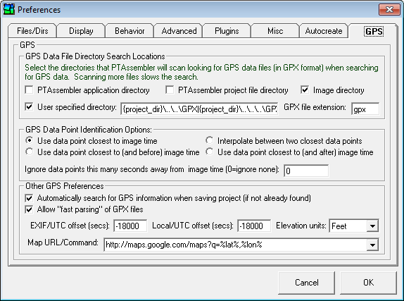
- PTAssembler application directory. If checked, PTAssembler will search the directory in which it is installed for GPX files when looking for GPS data.
- PTAssembler project file directory. If checked, PTAssembler will search the directory in which the current project file is saved for GPX files when looking for GPS data.
- Image directory. If checked, PTAssembler will search the directory in which the first image in the current project is saved for GPX files when looking for GPS data.
- User specified directory. If checked, PTAssembler will search the directory (or directories) specified in this field for GPX files when looking for GPS data. A single directory may be specified (e.g. c:\mygpxfiles) or multiple directories may be specified, seperated by a "|" character (e.g. c:\mygpxfiles|c:\myimagefiles). In addition to specifying a full qualified path (e.g. c:\mygpxfiles) you can also use three tokens ({project_dir}, {image_dir} and {app_dir}) that are evaluated by PTAssembler when searching for GPX files. For example, "{project_dir}\..\GPX" tells PTAssembler to search for GPX files in a directory called "GPX" that exists one level higher than the project directory.
- GPX file extension. PTAssembler will look at files with this extension when looking for GPX files.
- GPS Data Point Identification Options. This frame contains options that govern how PTAssembler cross-references the time contained in the image data and/or specified on the properties screen with the time in the GPX data files. It is often the case that the GPX data may not contain a track point at precisely the same second as the image time, and so PTAssembler can be configured to use the data from the nearest point (before and/or after the image time), or to interpolate between the two nearest points.
- Ignore data points this many seconds away from image time (0=ignore none). Track points that are further away than this many seconds from the image time are ignored by PTAssembler. If set to 0, no track points are ignored.
- Automatically search for GPS information when saving project (if not already found). If checked, PTAssembler will search for GPS information when saving a project file if the GPS information has not already been populated or specified on the properties screen.
- Allow "fast parsing" of GPX files. If checked, PTAssembler will attempt to perform a fast parsing of GPX files. This will work correctly if the trackpoints within the file are sorted in chronological order and allows PTAssembler to reduce the amount of time necessary to identify GPS coordinates when searching large files. This feature will not work correctly if the GPX files do not contain trackpoints in chronological order.
- EXIF/UTC offset (seconds). This is the number of seconds difference between "Coordinated Universal Time" or UTC (usually recorded by GPS units), and the time recorded in the camera's EXIF data. PTAssembler adds this value to the time recorded by the GPS unit when cross-referencing the time data from the GPX file and the image/camera time. For example, the east coast of the United States is 4 or 5 hours behind UTC (varies depending on daylight savings time). A value of -18000 specifies an offset of 5 hours and a value of -14400 specifies an offset of 4 hours. This value can also be specified in an external file as described here.
- Local/UTC offset (seconds). This is the number of seconds difference between UTC (usually recorded by GPS units), and the local time at the photographed location. PTAssembler uses this value (in conjunction with the EXIF/UTC offset value) to establish the relationship between local time, EXIF time and UTC time. This value is used when calculating sunrise/sunset times on the properties screen. This value can also be specified in an external file as described here. .
- Display elevation in Select meters or feet for elevation display.
- Map URL/command Use this drop-down box to enter a URL (or select from one of the preconfigured URLs) to be launched when the "Map GPS Data" button on the properties screen is clicked. If the URL contains the strings "%lat%" and "%lon%", these are replaced with the currently specified values for latitude and longitude before the URL is launched.
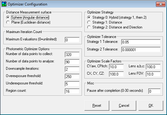
The Optimizer configuration screen allows you to modify the way in which PTAStitcher optimizes the project. Note that the default settings are almost always the most appropriate settings. The default settings can be recalled by using the "Reset" button on this screen.
- Distance Measurement Surface. If control point distances are measured on a plane, then points in regions where the projection is "stretched" (e.g. the edges of a wide rectilinear image) will show much larger distances than those in the center. As a consequence, these points become more important to the optimizer, which may result in a better fit for points in these "stretched" regions, but a generally lower overall quality of fit. It is usually best to use the spherical measurement surface as this gives all points equal importance regardless of their position in the output image.
- Optimizer Strategy. Changes the metric that the optimizer uses to evaluate how well it is converging upon a solution. A hybrid strategy (Strategy 0) usually gives the best combination of speed/accuracy.
- Optimizer Tolerance. Specifies the amount at which the optimizer stops iterating and/or moves to the next strategy.
- Maximum Iteration Count. Specifies the maximum number of iterations that the optimizer is allowed to make. A value of zero allows the optimizer to continue iterating until it has converged upon a solution (see also optimizer tolerance, above).
- Pause after completion. By default, the optimizer window closes immediately after the optimizer completes. A non zero value will force the optimizer window to remain open so that you can inspect any messages that the optimizer produces.
- Optimizer Scale Factors. These options cause the optimizer the adjust the scale of variables during optimization. Scale factors larger than 1 are appropriate for variables that generally have small values, such as the lens distortion parameters. The default factors should work well under most circumstances, but adjusting these factors may help the optimizer converge to a good solution in cases where a good solution cannot be found using the default factors. This is an advanced option, and there is usually no reason to adjust these default values.
- Photometric Optimizer Options. These options pertain only to the way in which exposure, vignetting and whitebalance (i.e. photometric) adjustments are estimated. Hover the mouse cursor over each field for a description of what each field adjusts.
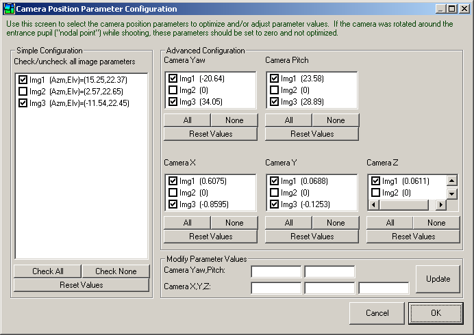
The Camera Position Parameter screen allows you to allows you to choose which camera position parameters to optimize, and reset or update any camera position parameter values. This screen, and how to use it, are described in more detail on this page.
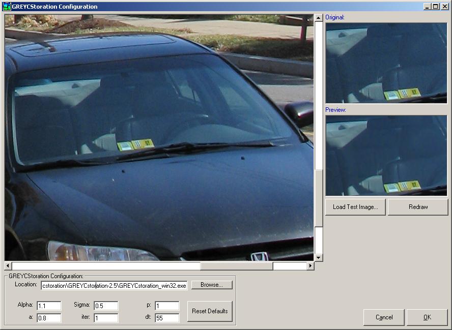
The GREYCstoration screen allows you to specify the location of the GREYCstoration executable and configure the parameters it uses when it is invoked from within PTAssembler to pre-process images. Before using this screen, you must specify the location of the GREYCstoration program using the "Browse..." button to locate the GREYCstoration program on your machine.
The six boxes at the bottom of the screen (Alpha, Sigma, p, a, iter, dt) are used by GREYCstoration to determine how to process images. For documentation on these parameters, what they mean, and how they impact GREYCstoration's noise reduction results, please consult the GREYCstoration documentation available on the GREYCstoration website (See the downloads section below). The "Reset Defaults" button resets the values for these six parameters to their defaults.
The "Load Test Image" button allows you to load an image into the main viewer on this screen. You can interactively determine what any adjustments to the six GREYCstoration parameters will have on the image, by drawing a rectangle on the large viewer (press the left mouse button, drag the mouse to draw a rectangular region, and then release the left mouse button). The selected region is transfered to the "Original" viewer window, and the same image (after processing by GREYCstoration) is displayed in the "Preview" viewer window.
After adjusting the six GREYCstoration parameters, you can use the "Redraw" button to create an updated preview or you can select another region to view by drawing a rectangle in the main viewer window.
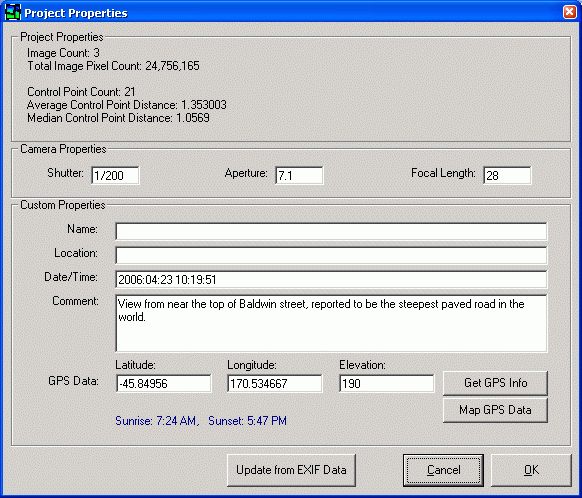
The properties screen displays information about the current project. The information is used for informational purposes only, so you don't need to fill in any data on this screen to create a stitched image. However, the information on this screen can be useful for cataloging and/or labeling projects. The screen is divided into three panels: Project properties, Camera properties, and Custom Properties. The information on this screen is stored in the PTAssembler project file.
Project properties. This panel displays information such as the number of images in the project, the total number of pixels that all images in the project contain, the average control point distance, etc. This information is calculated by PTAssembler and cannot be edited by the user.
Camera properties. This panel displays the aperture, shutter speed and focal length information. If PTAssembler finds EXIF data in the images in the project, then it can populate these fields automatically. Clicking the "Update from EXIF data" button will cause PTAssembler to examine the first image in the project, and populate these fields using the EXIF data that it finds. These fields can also be edited, so data can be entered manually if desired.
Custom properties.
- Name, Location, Date/Time, Comment.
The name, location and comments fields can be used
to record any textual information the user inputs. The Date/Time field can also accept
any textual information, such as "Sep 2005", "September 29, 2005,
late afternoon" or "2005/09/29 17:35:00". However, the
Date/Time field can also be populated by clicking the "Update from EXIF Data"
button (assuming, of course, that the images in the project actually contain EXIF data).
- GPS Data.
PTAssembler may be able to automatically populate the three GPS data fields
(Latitude, Longitude and Elevation) depending on available information
(more details below). Alternatively, all three fields can be entered (or edited) by
the user. The longitude and latitude data are expected in decimal format
(WGS 84 Datum), and the elevation is in meters or feet (depending
on the setting on the GPS tab of the preferences screen).
If longitude and latitude and Date/Time are present on this screen,
PTAssembler will compute and display the local time for sunrise and sunset.
PTAssembler is capable of populating the GPS fields automatically if the first image in the project contains EXIF data with GPS information. Alternatively, PTAssembler can use GPS data contained in GPX files. Most GPS units have a "track" or "track-log" feature that continually records the current position of the user. Similarly, there are applications that run on modern smartphones to record track logs. This data can be downloaded from the GPS/Phone and stored as a GPX file using any one of a large number of freeware and shareware applications. Once downloaded, the GPX data file contains track-log information about latitude, longitude, elevation and time. By cross-referencing the time information from the GPX data with the time specified on the Date/Time field (i.e. the camera's local time) on this screen, PTAssembler can assign the longitude, latitude and elevation fields automatically. Note that the Date/Time field must be populated using a format that PTAssembler can understand, in order for it to be able to cross-reference the date information. Formats like "YYYY:MM:DD hh:mm:ss" (e.g. "2005:09:29 18:30:00"), or "YYYY-MM-DD hh:mm:ss" (e.g. "2005-09-29 18:30:00") are acceptable.
To automatically populate the GPS data on this screen, PTAssembler needs to know where to find the GPX file(s). This can be configured, along with a number of other options, on the GPS tab of the preferences screen. Once configured, the GPS data can be automatically assigned by clicking the "Get GPS Info" button. The "Map GPS Data" button will launch a URL in the default web-browser to plot the GPS location using one of several online mapping services. The computer needs to be connected to the Internet in order for this feature to work correctly. The URL that is launched can be modified/configured using the GPS tab of the preferences screen.
Most GPS units store time and date information in UTC format. However, most digital cameras store time in local time. In order for PTAssembler to be able to cross-reference the time recorded by the GPS unit with the local time recorded in the EXIF data (or specified by the user on this screen), a "time offset" value must be specified on the GPS tab of the preferences screen. It is also worth noting that some GPS units (e.g. Garmin Etrex) remove time information from track-log data when "saving" the active track-log. Once the time information has been removed from the track-log, the data is useless for PTAssembler. For this reason, it is recommended that you do not use your GPS unit's "save" feature unless you are sure that it doesn't erase the time data.
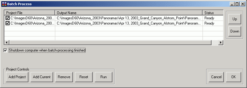
The batch processor allows you to create multiple panoramas in succession without intervention. You can add the current project to the list by clicking the 'Add current' button or another project by clicking the 'Add project' button. You can also drag-and-drop project files onto this screen. The project files must be ready for final creation (i.e. control points have been set and the optimizer has been run). When the project is added to the list, you will be prompted to choose a name for the final image.
To temporarily include/exclude a project, you can check/uncheck the box next to the project name in the list.
If the 'Shutdown computer' box is checked, PTAssembler will attempt to shutdown and poweroff the computer when all projects are finished processing.
To start processing, press the 'Run' button.
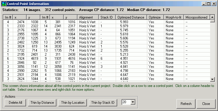
This screen shows information about all the control points in the project. It is similar to the table displayed on the Step 3 screen, but shows information for all control points, rather than just the two images loaded in the viewer windows on the Step 3 screen.
Clicking on a column header to sorts the table. Double-clicking on a row loads the images corresponding to a control point in the viewers on the Step 3 screen, and centers the control point in the viewer windows.
If one or more rows are selected, right-clicking displays a popup menu with the following options:
- Delete control point(s)
- Choose whether the control point(s) should be used for "morph-to-fit" (See morph-to-fit options on Step 2 screen)
- Choose whether the control point(s) should be used when optimizing
Delete All. Removes all control points from the project.
Thin by Distance. Removes the control points with the highest optimized distance from each image pair if each image pair has more than the specified number of control points. For example, if the Thin amount (selected in the drop-down box next to the "Thin" buttons) is set to '5', PTAssembler iterates through every image pair that share control points. For each image pair where there are more than 5 control points, the extraneous points with the highest optimized distances are removed. If an image pair contains 5 or fewer control points, no control points are removed from the image pair.
Thin by Location. Removes the control points which are located closest to others in the same image pair if each image pair has more than the specified number (selected in the drop-down box next to the "Thin" buttons) of control points. This can often be useful for removing control points produced by the control point picker program, which sometimes "clusters" a large number of points in a small area.
Refresh. Updates the list to refresh any additions or deletions that may have been made on the Step 3 screen.
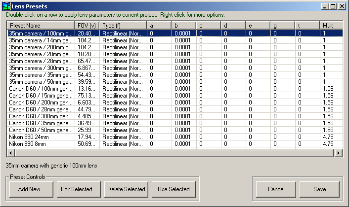
This screen allows you to work with lens presets. Lens presets are a convenient way to store and recall the appropriate parameters (FOV, a, b, c, etc.) for a particular lens. You can add, edit or delete presets using the buttons on this screen. To use a preset in a project click the 'Use Selected' button and the preset values will be used to populate the appropriate fields on the Step 2 Screen.
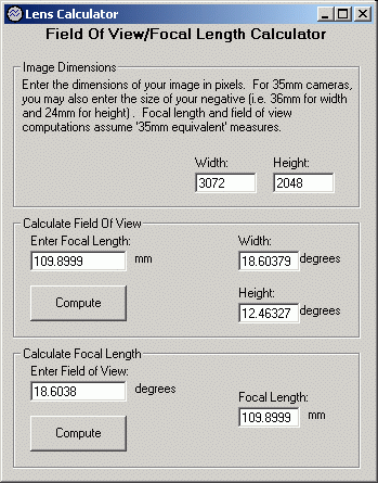
The stand-alone calculator can be used to compute field-of-view values from focal length, and vice-versa. It does not need to be used in order to create a stitched image, but may be useful for making calculations to determine appropriate lens parameters.
The numeric transform dialog can be used to reposition the images in the project by adjusting their yaw, pitch and roll values. Note that this is not as simple as adding or subtracting values from the yaw, pitch and roll values for each image, because this would not maintain the relative positioning of the images in the project. The numeric transform adjusts these values so that the relative positioning of all images is maintained.
In addition to the menu items listed below, you can add any number of additional items to the end of the Tools and Help menus. See the 'usertools.txt' and 'links.txt' files in PTAssembler's directory for more details.
- File menu
- New Project. Resets values and starts a new project.
- Open Project. Opens a previously saved project.
- Save Project. Saves the project using current project name.
- Save Project as. Prompts for a name, and saves project. If shift key is pressed while selecting this option, PTAssembler suggests a new name using the first and last image names in project.
- Write Project Execution Script. Writes a project execution script to the temporary directory. This script can be executed manually by double clicking on it, even if PTAssembler is no longer running.
- Add Images. Adds images to a project.
- Properties. Displays the properties screen.
- Preferences. Displays the preferences screen.
- Exit. Ends program.
- Recently Used files. Recently used projects are added to the bottom of this menu. Click to load.
- View menu
- Step 1. Shows the Step 1 Screen.
- Step 2. Shows the Step 2 Screen.
- Step 3. Shows the Step 3 Screen.
- Step 4. Shows the Step 4 Screen.
- Step 5. Shows the Step 5 Screen.
- Show exposure/whitebalance/vignette adjustments. Shows the Photometric adjustment screen.
- Show all control points. Shows the Control Point Information Screen.
- Tools menu
- Set Reference Point. Shows the Reference Point Picker Screen.
- Show lens presets. Shows the Lens Presets Screen.
- Show lens calculator. Shows the Lens Calculator.
- Micro-position all Control Points. Micro-positions (See preferences) all the control points in the current project.
- Apply parameters from another project. Applies the parameters from another project into the current project. Optionally imports control points from another project.
- Remove Control Points From Non-Sequential Images. Removes all control points that don't belong to numerically adjacent images. For example, if a control point connects image 1 and 2 it is kept (1 and 2 are adjacent), but a control point that connects images 2 and 5 or a control point that connects images 7 and 4 are removed.
- Batch Process. Shows the Batch Processing screen.
- Numeric Transform. Shows the Numeric Transform screen.
- Create Layout Image. Generates a small image showing thumbnail versions of all the images in the project arranged in a grid. PTAssembler places the images at the appropriate locations in the grid based on the yaw, pitch and roll values for the images in the project. An example layout image is shown in the introduction to this document.
- Display Last Generated Preview Image. Shows the last preview image generated by PTAssembler using the preview viewer.
- Display Last Generated Final Image. Shows the last final image generated by PTAssembler using your system's default image viewer.
- Show Current Project File in Notepad. Shows the current PTAssembler project file in notepad.
- Explore Current Project Directory. Opens Explorer at the directory that contains the current project's images.
- Help menu
- Help. Shows this document.
- Show wizard now. Shows PTAssembler's wizard to guide the user through the steps required to create a stitched image.
- Purchase/Register. Shows the registration screen, used to purchase PTAssembler. This screen provides a link to the website where you can purchase a license code. Once you have received the code via e-mail, you can return to this screen, and enter the code into the appropriate field to unlock the full, unrestricted version of PTAssembler.
- Check Installation. Checks to make sure that all required PTAssembler files are found, and reports version numbers and build dates. Also reports on installation status of optional helper programs.
- Show ptasmblr.ini. Shows PTAssembler's "initialization" file used to retain settings when the program is closed. This information may by needed when submitting a bug report.
- About. Displays program information.
- View readme.txt Shows information about PTAssembler, including installation help and version change information.
- Links. Several links to web sites with additional information about PTAssembler are provided at the end of this menu.
The Autocreate feature automates the entire process of creating a stitched image, from control point placement, to lens parameter selection, through optimization, stitching and blending. No manual work is necessary. A final stitched image can be "autocreated" by loading the source images on step 1, and then clicking the blue "Autocreate" button.
Autocreate replicates the steps that a typical user takes when creating a stitched image using PTAssembler. All manual steps are automated using PTAssembler's internal logic, and/or helper programs. For example, control point placement is one of the most time consuming parts of creating a panorama, and this is automated using a control point picker program, which is executed by PTAssembler. PTAssembler takes care of running the control point picker program and reading the control points that it creates. Similarly, setting the reference point is automated by PTAssembler's logic, as is all project optimization, and autosizing.
Autocreate relies upon two helper programs: a Control Point Picker program and a blending program. While PTAssembler will operate without these helper programs, they are mandatory in order for the Autocreate feature to work correctly. See the downloads section at the bottom of this page for information on where to download these programs. If Autocreate is configured (via the preferences screen) to stack images, then a stacking program is needed as well.
Autocreate should work well for most images, but it isn't infallible. Computers don't "see" images the way humans do, and may occasionally choose "bad" (i.e. incorrect) control points. PTAssembler attempts to find and remove any bad control points but this is not always possible. In some cases the images may not contain enough features for Autocreate to identify control points. In either of these situations, Autocreate may not produce the best results, and you may have to manually add or edit the control points. Another important caveat is that not all images contain enough information to allow PTAssembler to determine the lens field of view (one of the key parameters required for the optimizer and stitcher to operate). If this is the case, PTAssembler can either (1) attempt to estimate the correct value, or (2) you can specify a value manually using the preferences screen. The second approach is recommended for best results. These choices can be configured on the "Autocreate" tab of the preferences screen.
There are a number of artistic issues to consider when using Autocreate. There is no one, single "correct" result when stitching images together. The choice of image projection format, and horizon placement are two examples for which there is no right or wrong decision. PTAssembler makes what it considers to be reasonable choices but these may not be what you expect and/or desire. Of course, all of these limitations (technical or artistic) can be overcome by working with PTAssembler manually.
Currently, the Autocreate feature doesn't work with fisheye lenses, and requires that all images have the same size and were taken with the same focal length.
Although the Autocreate feature is designed to run automatically (i.e. without any user intervention), a number of options can be configured using the "Autocreate" tab of the preferences screen.
Holding the Ctrl key down while clicking the Auto-Create button will invoke the control point picker in "single-row" mode (currently only supported when using PTAPicker as the control point picker program). In this mode, the control point picker program only examines the images immediately before and after the current image when identifying control points. This is only appropriate for "single-row" panoramic images, but can speed up the collection of control points.
Note that PTAssembler also offers a closely related capability, Autoalign, which can be used to create a series of aligned images.
The Autoalign feature is a variant of PTAssembler's Autocreate feature, but rather than creating a single blended image as output, it is designed to create a series of precisely aligned or "registered" images. To invoke PTAssembler's Autoalign feature, hold the shift key down while pressing the blue "Autocreate" button on PTAssembler's Step 1 screen.
If you take a sequence of images of the same scene using a camera mounted on a tripod, with a remote/cable release, and without moving the tripod between exposures, the resulting images will be perfectly aligned or registered; the same elements in the scene (trees, houses, roads, signs, etc.) will appear at precisely the same location in each image in the sequence. However, if the camera is moved (even slightly) between exposures or the focus is changed, then the images are no longer perfectly aligned, and elements in the scene appear at different positions in the images.
There are at least two scenarios where it is important that a sequence of images be aligned or registered: "exposure blending" and "focus blending". In both of these techniques, it is important for the images to be aligned correctly. However, it is not always possible for the images to be captured in such a way that they are aligned. For example, the position of elements within the scene is likely to differ between exposures if the focus setting is changed. This is because the angular field of view (FOV) captured by most modern camera lenses changes with the focus setting, and the result is that elements in the scene appear to shift from one exposure to another. The purpose of PTAssembler's Autoalign feature is to produce a series of aligned images that are suitable for processing with other applications that require aligned images.
PTAssembler's Autoalign feature can align or register a series of images, accommodating and correcting for changes in yaw, pitch, roll and FOV for each image in the series. When Autoaligning a series of images, PTAssembler will produce as many output images (in TIFF format) as input images. The input images should all be of the same scene, and have the same dimensions (width x height).
Autoalign attempts to (1) find control points for all images, (2) perform the appropriate optimization steps, and (3) create output images that are the same size as the input images. Autoalign can also (if configured on the preferences screen) invoke the stacking process using the resulting aligned images as input for the stacking program.
Currently, Autoalign only works for rectilinear lenses like those typically found on almost all modern cameras...fisheye lenses/images will not work correctly. Also, PTAssembler will attempt to auto-align all images in the project into a single stack of aligned images, so you should only include those that should be aligned as part of single set.
When processing images to create a final panorama (i.e. when the "create" button is pushed), PTAssembler invokes one or more external programs to produce a resulting image. In its simplest mode of operation, PTAssembler invokes the stitching program to create a single output image from multiple input images. No other functions are performed and no other programs are necessary.
However, PTAssembler's capabilities can be significantly enhanced with additional, optional, programs. Specifically, PTAssembler can be configured to "preprocess" the images before they are processed by the stitcher, and to "postprocess", "layer blend", "stack", "blend" and/or "crop" the images produced by the stitcher. The following diagram illustrates the complete set of processes via which images can be transformed by PTAssembler. These options can be configured on the Processing Options screen.
For more description and illustrated examples of PTAssembler's workflow, please consult this document.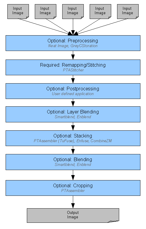
PTAssembler Process Flow. Blue boxes represent processes that can be invoked by PTAssembler
Input images (supplied by the user on the Step 1 Screen) are processed in sequence by the processes represented by the blue boxes in the diagram above. With the exception of the "remapping/stitching" step all of the other processes are optional and can be enabled or disabled by the user. Some of the processes can only be performed depending on the output format and/or configuration of a process executed earlier in the sequence (described below).
Workflow Processing Steps. Depending in the output file format and program configuration, one or more of the following processing steps are performed in order by PTAssembler.
Image pre-processing can be performed by either of two "noise-reduction" programs. These programs can be invoked regardless of the chosen output format from the stitching program. Image pre-processing is performed prior to the images being used by the stitching program. Image pre-processing does not modify the input images, but rather creates intermediate, temporary images that are subsequently used by the stitching program.
Remapping/Stitching is performed on the input images (or images created by the pre-processing program) and is where the images are processed so that they align correctly and can be flattened into a final image. This step is performed by the stitching program (PTAStitcher, by default).
Image post-processing can be performed by any user-defined application. Post-processing can be invoked regardless of the chosen output format from the stitching program.
Layer Blending can be performed only if stacking is also performed. If layer blending is configured (via the Step 1 screen), images that share the same layer ID are blended together in this step. This is an advanced option and not usually necessary/recommended except for unusual circumstances where stacking after blending (see below) does not produce satisfactory results.
Stacking can be performed only if the output format is "Multiple image TIFF" or "Blended, single layer TIFF" format. If configured, the stacking program will convert all images with the same Stack ID (specified on the Step 1 screen) into a single image. For example, consider a project that contains 18 images, divided into 6 stacks with 3 images per stack. The remapping/stitching step will use 18 images as input, and produce 18 output images. The stacking step uses these 18 images produced by the stitching step and will produce 6 images (one for each stack) as its output. Note that stacking is an optional step and is only performed if (a) stack IDs are assigned and (b) there are more than one image per stack. (If layer blending is enabled, then the number of images that are stacked depends on the output from the layer blending step.)
Blending is only performed if the output format is "Blended, single layer TIFF". The blending program accepts multiple input images that have been produced by the stitcher (and optionally post-processed, layer blended and/or stacked). The purpose of the blending program is to try and hide any evidence of seams resulting from misalignments, lighting shifts, etc. Blending programs use "intelligent" algorithms to blend two or more adjacent images as seamlessly as possible.
Cropping can be performed on the image(s) produced by the blending, stacking and/or stitching program if the output format is "Multiple image TIFF" or "Blended, single layer TIFF". The cropping step is is designed to remove any extra "black-space" around the edge of the image. The cropping program ("TIFFCrop") is distributed and installed with PTAssembler. Cropping can be enabled or disabled using the preferences screen or the Processing Options screen. See A Note About Output Size for more information about cropping.
Workflow Processing Examples. The following diagrams illustrate several examples of how PTAssembler process images under different configurations.
Unblended Image Output. In its simplest mode of operation PTAssembler can be configured to operate without the use of any optional processing. For example, when JPEG or PSD format is selected, and no pre or post processing is chosen, the following operations are performed. In this example, four images are used by the stitching program which produces a single file as output. If the output format is JPEG or TIFF, the stitching program does not perform any blending between adjacent images...the images are positioned correctly relative to each other, but the stitcher simply overlays one image next to another to join the four images into one composite. Superior blending results are almost always achieved using a blending program as described later in this section. If the output format is a multi-layer PSD or PSB format, then each input image is placed on a single layer in the resulting image, and no blending is performed.
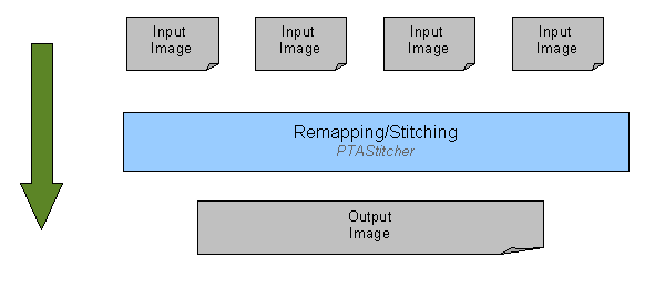
PTAssembler Process Flow. Single, flattened image output
Blended Output. Below is a more complicated example, illustrating the processing that takes place when Blended Tiff output is selected, and optional cropping is also selected. In this example, four input images are used by the stitching program to create four "remapped" intermediate images. These four intermediate images are then used by the blending program to create a single intermediate blended image. Lastly, the cropping program uses the intermediate blended image to create a final output image.
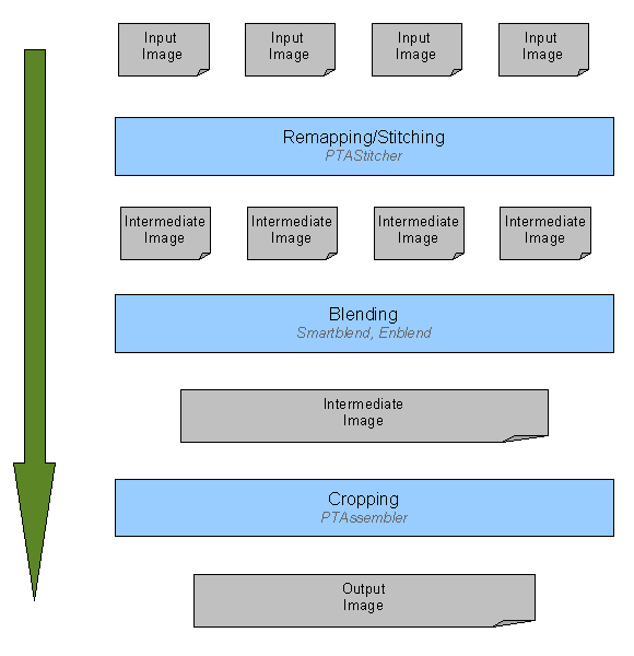
PTAssembler Process Flow. Blended TIFF output
Stacked and Blended Output. The next example is more complex in that the input images are stacked prior to being blended. In this example, the project contains 10 images, and 5 stacks. Each stack contains two images (typically each image in a stack has a different exposure or focus setting). The output from the stacking program is 5 images, which are used by the blending program to create a single blended image. As above, this blended image is used by the cropping program to create a final output image.
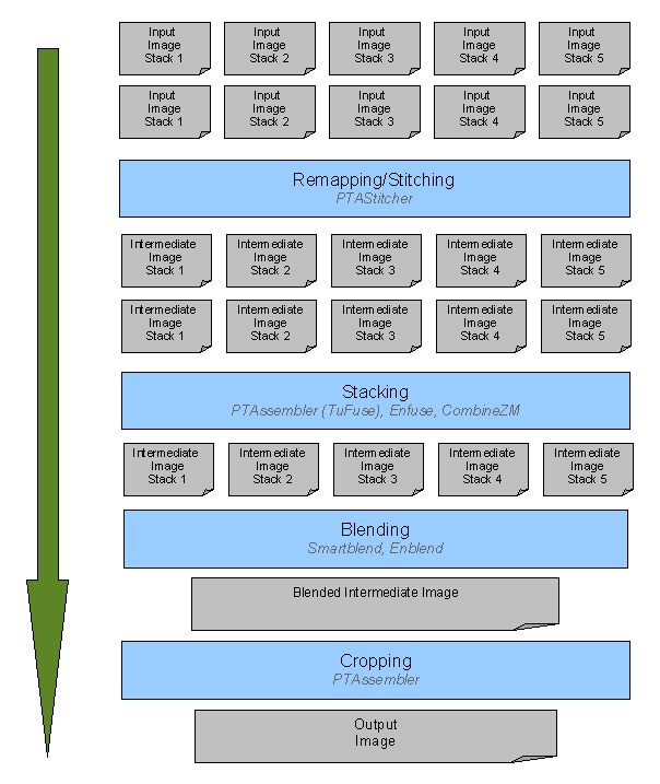
PTAssembler Process Flow. Stacked and Blended TIFF output
Layer Blended, Stacked and Blended Output. This last example illustrates the most complex processing workflow available within PTAssembler. It is similar to the stacked and blended example above, but adds an additional "layer blending" processing step. This is an advanced option suitable for specific circumstances where stacking prior to blending does not produce optimal results. In these cases, the results may appear more natural/pleasing if some of the images are "layer blended" prior to stacking.
Similar to the example above, this project contains 10 images, and 5 stacks. However, in this example each image in the stack has been assigned a layer ID. The layer blending stage uses the blending program to blend images that share the same layer ID. In this example, the result of the layer blending stage is 4 images. These 4 images are then stacked into 2 images, and then blended together into a single image before final cropping.
Note that the arrangement of images into stacks and layers is important in determining how PTAssembler invokes the stacking program with the output from the layer blending program. In this example, PTAssembler determines that layer 1 and layer 2 should be stacked together, and that layer 3 and layer 4 should be stacked together. It is able to make this determination by looking at the stack IDs assigned to the images in each layer. Because layer 1 and 2 both contain images from the same stacks (stacks 1 and 2), and because layer 3 and 4 both contain images from the same stacks (stacks 3, 4 and 5), PTAssembler knows that layer 1 and 2 should be stacked, and that layer 3 and 4 should be stacked.
If, on the other hand, the stack and layer IDs were configured differently and the images used to produce layer 1 and layer 2 did not come from an identical set of stacks, then PTAssembler would not know that layer 1 and layer 2 should be stacked, and they would be passed unprocessed to the subsequent (blending) step. Because of this, it is important to ensure that the correct stack and layer IDs are assigned to each image in your project if using the layer blending feature.
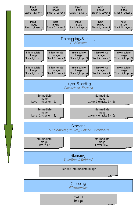
PTAssembler Process Flow. Layer Blended, Stacked and Blended TIFF output
PTAStitcher/PTMender/PTStitcher size. PTAssembler allows you to specify the output size on the Step 5 screen. The width and height choices govern the size of the image(s) created by the stitcher (PTAStitcher, PTStitcher or PTMender). However, when producing "Multiple image TIFF" or "Blended, single layer TIFF" output, the stitcher (PTAStitcher and PTMender) offers the ability to output "cropped TIFF" files (configured on the preferences screen). These cropped TIFF files are files that have had as much empty (black) space around the remapped portion of the image cropped away as possible without removing any of the actual useful image. In most circumstances, these "cropped TIFF" files can be generated considerably faster than uncropped files. Additionally, these cropped files typically have smaller dimensions than the dimensions requested on the Step 5 screen, although the useful (i.e. non-black) portion of the remapped image is the same size as it would have been if the image was uncropped.
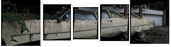
Five "cropped TIFF" images ("Multiple image TIFF" format) output from PTAStitcher
(cropped to remove as much extra "empty space" as possible)
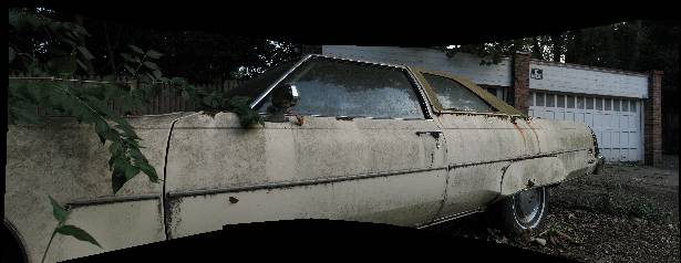
Images after blending with Smartblend
Blended output size. PTAssembler also offers the ability to process the blended files that are output from the blending program (Smartblend, Enblend or Multiblend) to crop any remaining "empty space" from around the edges of the image. This option is configured on the preferences screen and/or the processing options screen. As little of the image is removed as possible to ensure a resulting rectangular image with no empty/black space at its edges.
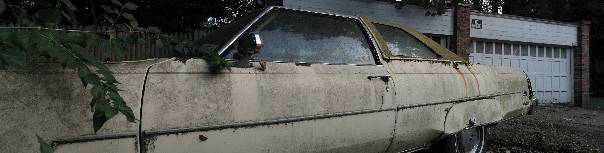
Final image after cropping to remove all extra "empty space" around image
If either of these options (cropped TIFF output from the stitcher, or final cropping of images output from Smartblend, Enblend or Multiblend) is used, the final image that is produced after all processing will typically have smaller dimensions than those that are specified in the height and width boxes on PTAssembler's step 5 screen.
Although PTAssembler is a graphical application, it can be launched from the command line (sometimes called a "command prompt"). The syntax for launching PTAssembler from the command line is as follows:
|
ptasmblr [action] [option] [image_file_1 image_file_2 image_file_3 ... image_file_n]
ptasmblr [action] [option] [image_file_start - image_file_end] ptasmblr [action] [option] [project_file] |
Image files scan be specified as a list (e.g. "img_0032.tif img_0033.tif img_0034.tif") or an "image pair" (e.g. "img_0032.tif - img_0034.tif"). If specified as a list, PTAssembler creates a project containing all files in the list. If specified as an image pair (i.e. using the "-" symbol between two image names), PTAssembler attempts to determine if the two images share a common numerical pattern, and if a pattern is detected, PTAssembler determines the intermediate image names. For example, "img_0032.tif - img_0034.tif" is expanded by PTAssembler to a list containing img_0032.tif, img_0033.tif and img_0034.tif. PTAssembler also checks to verify that the intermediate files exist before adding them to the project. If PTAssembler cannot determine the numerical pattern from the start and end images, it defaults to only adding the start and end images to the project.
If no action is specified, then PTAssembler starts and loads the image(s) or project specified on the command line. If no image(s) or project file is specified, then PTAssembler starts with an empty project.
The following actions are supported:
- /autocreate PTAssembler will run its Autocreate command after loading the images that are specified on the command line or in the project file specified on the command line. PTAssembler terminates immediately after autocreate has finished.
- /autoalign PTAssembler will run its Autoalign command after loading the images that are specified on the command line or in the project file specified on the command line. PTAssembler terminates immediately after Autoalign has finished.
- /stitch PTAssembler will run its Create command after loading the images that are specified on the command line or in the project file specified on the command line. PTAssembler terminates immediately after finishing. This is equivalent to pushing the 'Create' button on PTAssembler's step 5 screen. Note that the project must already contain values for yaw, pitch, roll, etc. in order for the stitching to work correctly.
The following options are supported:
- /nodisplay Causes PTAssembler not to display the (final or preview) image after autocreating or stitching the project.
- /overwrite Causes PTAssembler to overwrite an existing project file during autocreate (default behavior is to save project using a new/unique filename).
Examples of valid command lines that can be used to launch PTAssembler are as follows:
|
ptasmblr img_0001.jpg img_0002.jpg img_0003.jpg img_0004.jpg
ptasmblr img_0001.jpg - img_0004.jpg ptasmblr aproject.ptp ptasmblr /stitch aproject.ptp ptasmblr /stitch /nodisplay aproject.ptp ptasmblr /autocreate aproject.ptp ptasmblr /autocreate /overwrite aproject.ptp ptasmblr /autocreate img_0001.tif - img_0009.tif ptasmblr /autoalign img_0001.jpg img_0002.jpg img_0003.jpg |
PTAssembler can be further automated when used in conjunction with
PTAutomate, a
command line application that invokes PTAssembler's autocreate routine.
PTAssembler can assign location data (longitude, latitude and elevation) to your project by analyzing the EXIF data in your images, or by importing GPS coordinates from a GPX file (typically created by a GPS unit or smartphone). The location data is displayed on the Properties screen. Options for configuring how the location data is assigned are on the GPS tab of the preferences dialog.
When importing location data from a GPX file, PTAssembler needs to know the offset between the local time (typically) recorded by the camera's EXIF data, and the UTC time (typically) recorded by the GPS unit or smartphone. The "EXIF/UTC offset" field on the GPS tab of the preferences dialog can be used to specify this value and applies to all images in all projects. However, if you ever adjust the clock on your camera (e.g. because you traveled to a different time zone, or because of daylight savings time), then this value also needs to change accordingly. PTAssembler offers an optional alternate method for specifying this offset by entering the offset information into a file and storing that file in the same directory as the GPX file(s). This approach offers more flexibility as different values corresponding to different times can be entered, and different values for different cameras can be configured.
Whenever PTAssembler reads a GPX file to look for GPS data, it checks in the same directory as the GPX file for a file named "gps_exif_utc_offsets.txt". If it finds that file, it parses the file looking for information about the EXIF/UTC offset (and local/UTC offset) to use when interpreting the GPX data files in that directory. The data in the gps_exif_utc_offsets.txt file should be in comma-seperated (CSV) format with the following five fields:
- Start time in YYYYMMDDHHMMSS format (e.g. 20150917134500 is September 17, 2015 at 1:45PM).
- End time in YYYYMMDDHHMMSS format.
- EXIF/UTC Offset (in seconds).
- Local/UTC offset (in seconds).
- Camera model name (as recorded in EXIF data).
An example of the contents in a gps_exif_utc_offsets.txt file:
20150917000000,20150917104000,-14400,0,DSC-RX100
20150917104001,20150927230000,-18000,0,DSC-RX100
20150917000000,20150927230000,-14400,0,Canon EOS Rebel T6s
PTAssembler compares the camera model name in your image's EXIF data (e.g. "Canon EOS Rebel T6s" or "DSC-RX100") with the string recorded in the gps_exif_utc_offsets.txt file to determine which offset value to use. (PTAssembler shows the camera model name for your images on the Step 1 screen.) PTAssembler also checks the EXIF timestamp in your images against the start and end time fields to determine if your image falls between these times. If so, then PTAssembler will use the EXIF/UTC offset and Local/UTC offset specified in the file rather than the values specified as part of the GPS tab of the preferences dialog.
For example, consider the example gps_exif_utc_offsets.txt file above. If your project contains images taken with the DSC-RX100 camera and the first image in the project has a timestamp of September 21 2015 07:15:23 (i.e. 20150921071523), PTAssembler will use the values in the second line of the data, and use an EXIF/UTC offset value of -18000.
As hard as software developers try, most programs contain some bugs. If you find a bug in PTAssembler please feel free to contact the author (see PTAssembler's page for contact details). However, because PTAssembler is a "front-end" for a number of optional helper programs (Enblend, Smartblend, Multiblend, Panomatic, CPFind, etc.), it may be the case that the problem you are encountering is a problem with one of those programs, and not PTAssembler.
When reporting a problem, please give as much information as possible. A good bug report is one that allows the developer to reproduce the problem using the steps that you provide. A step-by-step recipe that allows the developer to replicate the problem is likely to result in a quick diagnosis and resolution. Reports with vague wording such as "I saw an error message" or "it doesn't work" make the diagnosis and resolution difficult or impossible.
If reporting a bug, please explain what happened, and provide the following items:
- PTAssembler project file. This is the file generated when using the "Save project" or "Save project as" menu items.
- The installation information. This information can be obtained by using PTAssembler's "Check Installation" menu item under the Help menu. The information can be copy-and-pasted into an e-mail or another document.
- ptasmblr.ini. PTAssembler's initialization file is used to save all program settings when PTAssembler is closed. This information can be obtained by using PTAssembler's "Show ptasmblr.ini file" menu item under the Help menu. The information can be copy-and-pasted into an e-mail or another document.
- Temporary project execution files. In the event that PTAssembler detects an error while stitching, it does not delete any temporary project files from the temporary directory after the error is encountered. PTAssembler presents a message on the screen alerting the user to the names and locations of these temporary files. These files record what should have happened, and where the process may have encountered a problem, and are extremely useful in diagnosing any problems. Note that these temporary files can be safely deleted at any time after execution has finished.
More detail is always better...Thanks!
- PTAssembler homepage.
- Panomatic: A program that automates the placement of control points (can be used as an optional control point picker plugin).
- Autopano: A program that automates the placement of control points (can be used as an optional control point picker plugin, but does not work on Windows 7/8).
- Enblend: A program that blends multiple TIFF output from the stitcher into a single TIFF using an advanced seam-blending technique (can be used as an optional blending plugin).
- Smartblend: A blending program similar to Enblend, but with a different seam-blending technique (can be used as an optional blending plugin).
- Multiblend: A blending program similar to Enblend, but with a different and faster seam-blending technique (can be used as an optional blending plugin).
- Neat Image: An image noise reduction program (can be used as an optional pre-processing plugin).
- GREYCstoration: An open-source image noise reduction program (can be used as an optional pre-processing plugin).
- Enfuse: An open-source stacking program to create an extended dynamic range images from multiple images of the same scene (can be used as an optional stacking plugin).
- CombineZM: A stacking program to create an extended focus images from multiple images of the same scene (can be used as an optional stacking plugin).
- Google: Where to look if any of the links here go bad.
- PTAssembler homepage.
- Detailed information on the image projections supported by PTAssembler.
- How to create panoramas when the camera was moved between shots using Camera Position Optimization.
- Detailed information about photometric adjustments using PTAssembler.
- PTAssembler discussion forums.
- TuFuse documentation/homepage.
- PTAPicker documentation/homepage.
- PTAssembler Stacking and Blending Examples.
- PTAssembler tutorial. A little out of date, but gives a good overview of working manually with PTAssembler.
- PTAutomate. Speeds up processing large numbers of panoramas.
- Max Lyons Digital Image gallery contains thousands of images created using PTAssembler.
- Joe Beda's introductory tutorial to PTAssembler
- John Houghton's tutorial on how to optimize manually.
- GPX information: Information about GPX format and software used to record GPS data.